Engine cylinder head having an improved intake port configuration, and engine incorporating same

a technology of engine cylinder head and intake port, which is applied in the direction of valve arrangement, cylinder, lift valve, etc., can solve the problems of difficult to improve the efficiency of air intake into the combustion chamber, and achieve the effect of reducing the flow resistance of air intake into the combustion chamber, and improving the efficiency of air intak

Inactive Publication Date: 2007-02-27
HONDA MOTOR CO LTD
View PDF8 Cites 13 Cited by
  • Summary
  • Abstract
  • Description
  • Claims
  • Application Information

AI Technical Summary

Benefits of technology

[0013]The air that enters the combustion chamber spreads rapidly outwardly, as noted, and advances smoothly along a curved surface of a circular end portion of the intake valve. The intake valve is located immediately downstream of the intake opening of the combustion chamber, and is curvedly shaped so as to spread like the foot of a mountain. In this arrangement, the intake flow resistance is reduced, and the efficiency of air intake into the combustion chamber can be improved.
[0014]Since the air enters the combustion chamber while expanding rapidly, even if a stagnation layer of air is formed near the wall surface of the intake port, the real air flow passage area enlarges to further improve the efficiency of air intake into the combustion chamber.
[0017]In a section downstream of the valve guide of the intake port, there is a location where the passage cross-section has an elliptical shape whose longitudinal diameter is significantly smaller than the transverse diameter, with the longitudinal-to-transverse diameter ratio being 0.9 or smaller. Therefore, the air flowing in through the intake port enters the combustion chamber after traveling, while spreading in the longitudinal direction, from a portion where the cross-section has an elliptical shape whose longitudinal diameter is smaller than the transverse diameter with the longitudinal-to-transverse diameter ratio being 0.9 or smaller, to a portion including the perfectly circular opening of the combustion chamber. Of all the air flowing into the combustion chamber, the air that comes along the curved wall surface, and that flows into the combustion chamber forming an angle more perpendicular to a circular end portion of the intake valve than the corresponding angles formed by the air that comes other than along the curved wall surface, can be transformed into an outwardly spreading air flow. Therefore, the air coming along the curved wall surface can advance smoothly along the curved surface of the circular end portion of the intake valve, immediately after entering the combustion chamber. In this manner, the resistance to the flow of air entering the combustion chamber is reduced, so that the efficiency of air intake into the combustion chamber can be improved.
[0019]Of the air flowing into the combustion chamber, the air that comes along the curved wall surface and that flows into the combustion chamber forming an angle more perpendicular to the circular end portion of the intake valve than the corresponding angles formed by the air that comes other than along the curved wall surface can be transformed, gradually and smoothly, into an outwardly spreading air flow immediately before reaching the intake opening of the combustion chamber. This allows the air coming along the curved wall surface to further advance along the curved surface of the circular end portion of the intake valve. In this manner, the resistance to the air entering the combustion chamber is reduced so that the efficiency of air intake into the combustion chamber can be further improved.

Problems solved by technology

In this arrangement, the intake air entering the combustion chamber is subjected to a large resistance so that it is difficult to improve the efficiency of intake into the combustion chamber.

Method used


Image

  • Engine cylinder head having an improved intake port configuration, and engine incorporating same
  • Engine cylinder head having an improved intake port configuration, and engine incorporating same
  • Engine cylinder head having an improved intake port configuration, and engine incorporating same

Examples


Embodiment Construction

[0030]A number of selected illustrative embodiments of the present invention will be explained in the following discussion, with reference to FIGS. 1 to 6.

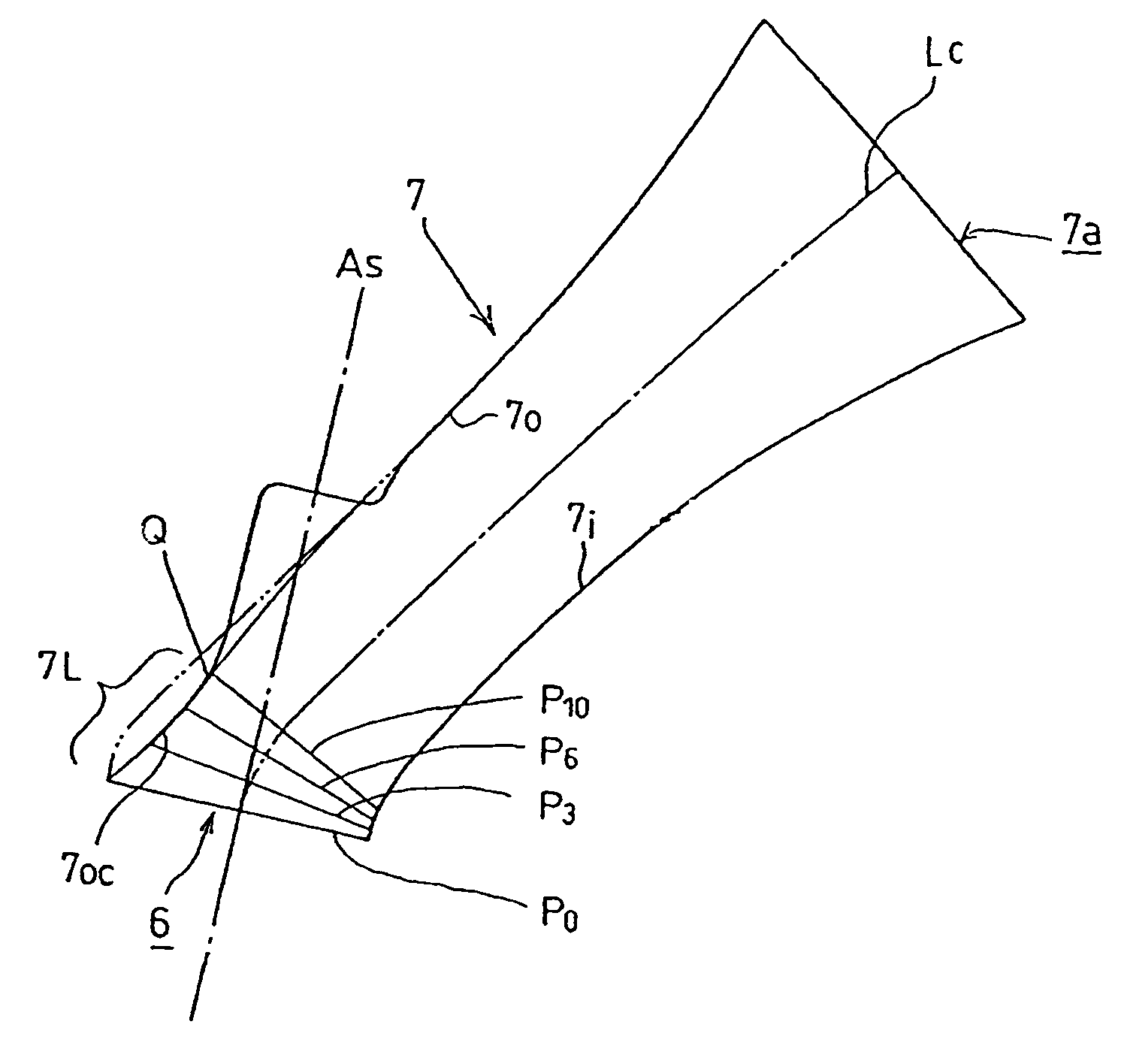
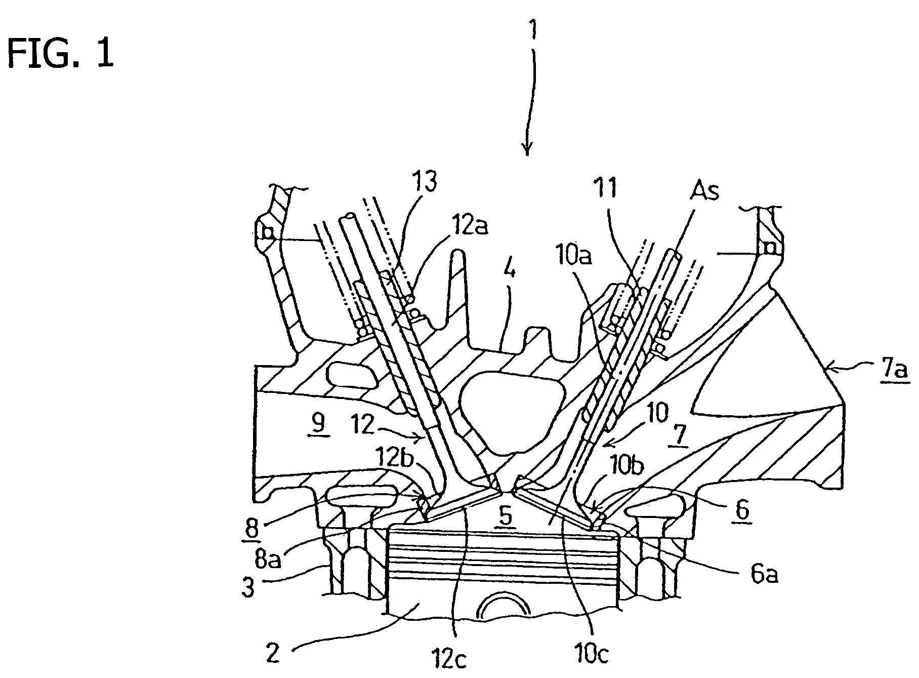
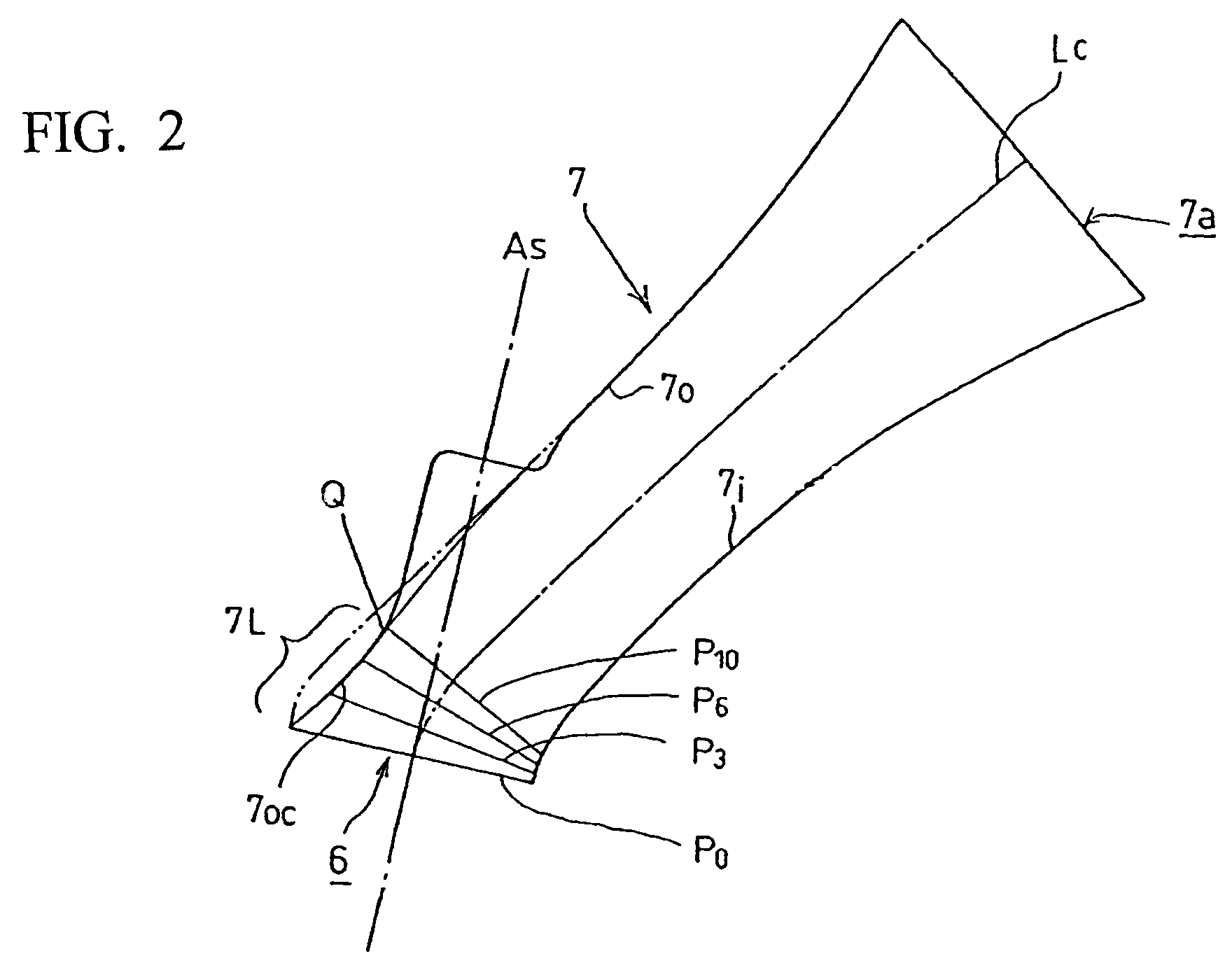
[0031]An internal combustion engine 1, according to the present illustrative embodiment of the present invention, is a four-stroke type of internal combustion engine, with four valves per cylinder. FIG. 1 is sectional view of a selected portion of the internal combustion engine 1, including a cylinder head 4 according to a selected illustrative embodiment of the present invention, and showing the valves 10, 12 supported by respective valve guides 11, 13 within the respective intake and exhaust ports 7, 9.

[0032]The cylinder head 4 is fitted to a cylinder block 3, in which a piston 2 is freely slidably fitted into a cylinder bore. The cylinder head 4 cooperates with a top surface of the piston 2 to define a combustion chamber 5, which is positioned above the piston 2 and adjacent to where the cylinder head 4 and the cylinder block 3...


PUM


Abstract

A cylinder head of an internal combustion engine is provided with an improved intake port configuration, that improves the efficiency of air intake into a combustion chamber. The engine includes an intake valve which covers an opening of a combustion chamber and which has a valve stem supported by a valve guide. The valve guide is fixed to a curved wall of an intake port leading from a hole in the side of the cylinder head to the intake opening of the combustion chamber. An intake port is configured so that the cross-sectional area thereof reduces with an increasing distance from the intake opening of the combustion chamber, and so that the passage cross-sectional area at a distance equal to about 10% of the total length of the intake port from the intake opening of the combustion chamber is 0.8 times the area of opening of the combustion chamber or smaller.

Description

CROSS-REFERENCE TO RELATED APPLICATIONS[0001]The present invention claims priority under 35 USC 119 based on Japanese patent application No. 2004-257816, filed on Sep. 6, 2004. The subject matter of this priority document is incorporated by reference herein.BACKGROUND OF THE INVENTION[0002]1. Field of the Invention[0003]The present invention relates to internal combustion engines. More particularly, the present invention relates to a cylinder head for an internal combustion engine, in which the cylinder head has an improved intake port configuration, and to an engine incorporating the improved cylinder head.[0004]2. Background Art[0005]The intake ports of internal combustion engines are formed in the cylinder head of the engine. Each intake port consists of a passage which leads from an inlet side, at an upstream end thereof, through the cylinder head and to an opening of a combustion chamber. During engine operation, intake air is guided into the combustion chamber through the inta...

Claims


Application Information

Patent Timeline
Patent Type & Authority Patents(United States)
IPC IPC(8): F02F1/42
CPCF02F1/4235
Inventor SATO, KATSUHIKO
Owner HONDA MOTOR CO LTD
Why Eureka
Try Eureka