Material-handling device for aerial work platform

a technology of material handling and work platform, which is applied in the direction of lifting devices, constructions, building aids, etc., can solve the problems of limited space and safety considerations, difficulty in maintaining visual contact with the load being lifted or the drop point, etc., to achieve the effect of facilitating the lifting or lowering of the operational height of each winch assembly, and facilitating the leveling of loads

Inactive Publication Date: 2007-02-27
MAN ELEVATOR MFG
View PDF11 Cites 28 Cited by
  • Summary
  • Abstract
  • Description
  • Claims
  • Application Information

AI Technical Summary

Benefits of technology

[0016]In one preferred embodiment of this invention, the material-handling device is a dual winch device comprising two winch assemblies and a winch control module to control either or both assemblies. In another highly preferred embodiment, the material-handling device is a fork lift device. It is most preferred that the material-handling device include both the dual winch device and the fork lift device whereby material-handling is interchangeable between the two devices. In any of these configurations, a worker on an aerial platform now has the ability to operate a material-handling device from that platform as well. This means one person is capable of accomplishing more work and performing that work more efficiently and effectively.
[0017]A certain desired embodiment finds the platform comprised of a rail support frame attached with respect to the boom, where the rail support frame has a boom side and an outer side, and a work basket that is removably mounted to the rail support frame. In one preferred form of this embodiment, the work basket is a front basket mounted o

Problems solved by technology

Although a certain amount of material can be carried with the workers in their aerial platform, space and safety considerations limit in most instances the number and size of such items.
Any aerial work apparatus used for typical material handling operations, on the other hand, can only be controlled by an individual on the ground.
The operator often has difficulty maintaining visual contact with the load being lifted or with the drop point for that load because of his distance from the loa

Method used


Image

  • Material-handling device for aerial work platform
  • Material-handling device for aerial work platform
  • Material-handling device for aerial work platform

Examples


Embodiment Construction

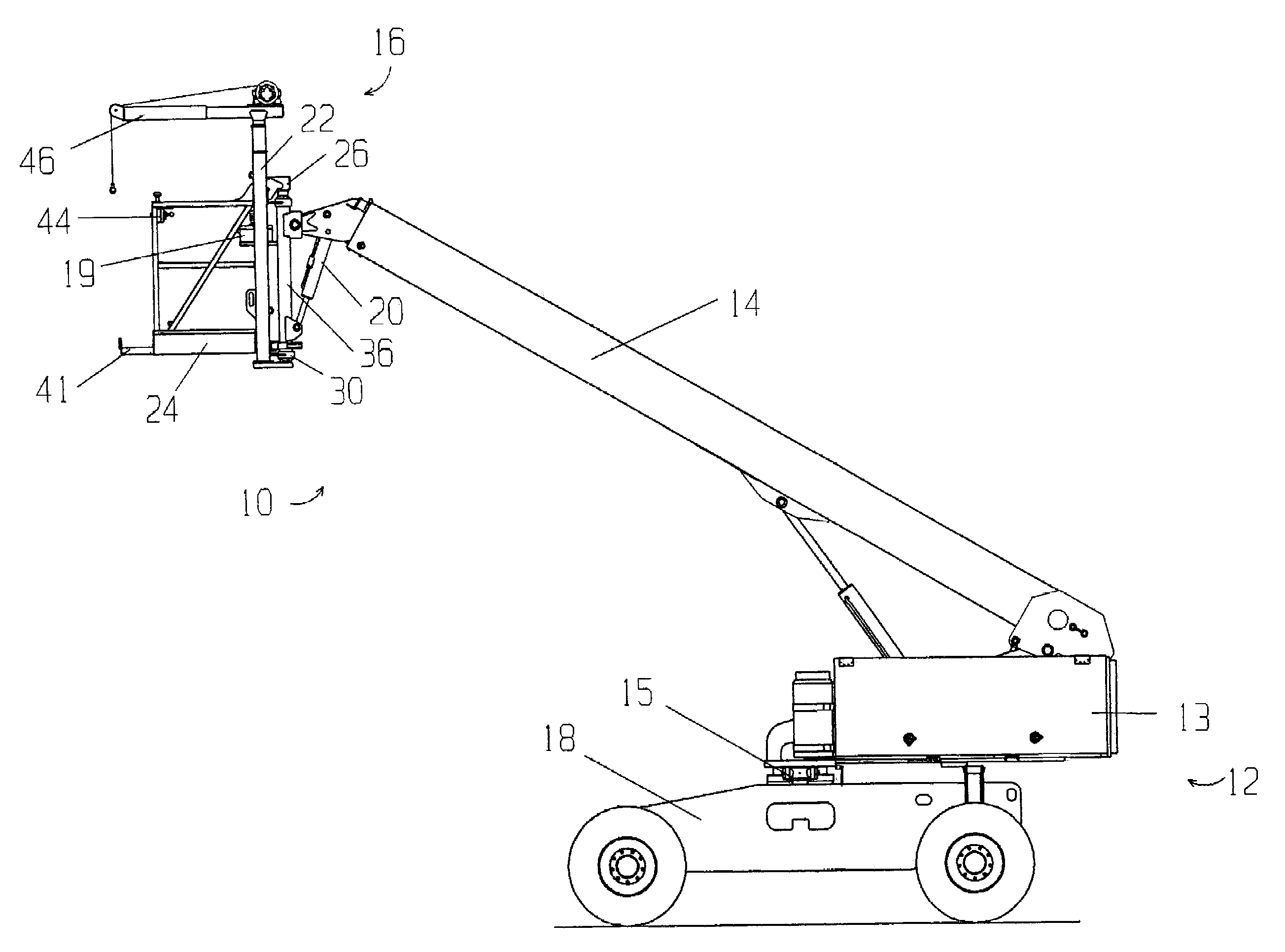
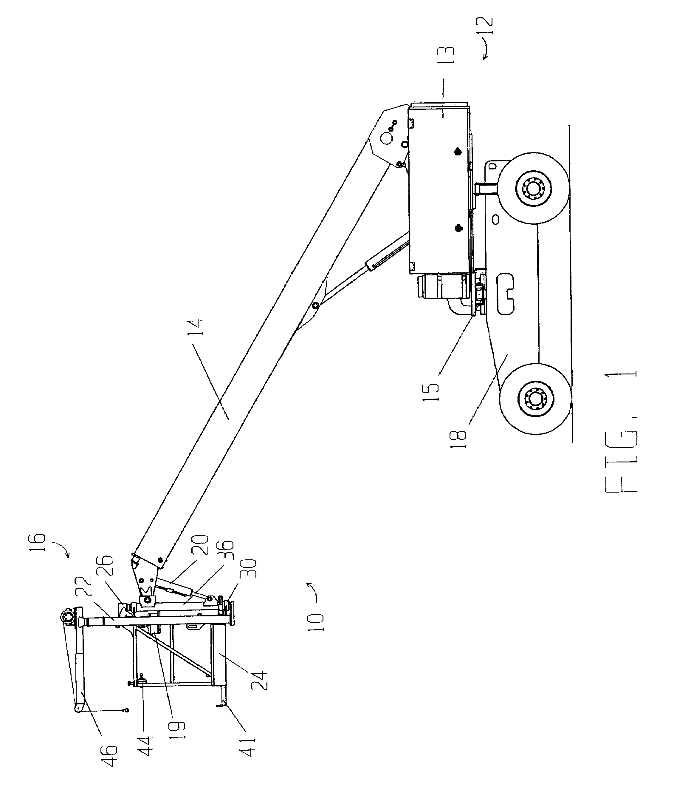
[0040]The drawings illustrate an improved aerial work apparatus 10 in accordance with this invention. As illustrated in FIG. 1, aerial work apparatus 10 is comprised of mobile chassis 12, boom 14 securely mounted to the chassis base 13 of mobile chassis 12, and aerial work platform 16 pivotably attached to the outer or distal end of boom 14. Mobile chassis 12 is of known construction, having a wheel base 18 under power that allows mobile chassis 12 to be driven in a controlled fashion. Controls for driving mobile chassis 12 are located both on chassis base 13 and on platform 16 as a portion of platform control module 19.

[0041]Boom 14 is capable of a variety of movements in a fashion known to those skilled in the art. Boom 14 can rotate 360° in either direction in a horizontal plane through the associated rotation of chassis base 13 about its base pivot 15. Boom 14 can also be selectively raised and lowered to a position measured by the angle formed by boom 14 with the ground. Furthe...


PUM


Abstract

An improved aerial work apparatus of the type having an aerial work platform attached to the distal end of a boom mounted to a mobile chassis comprising a material-handling device mounted with respect to the platform. Preferably, the material-handling device is either a dual winch device, a fork lift device, or material support feet. An aerial work platform comprising a rail support frame attached to the boom and a work basket is provided wherein the work basket can be interchanged between a basket in front of the boom and a basket positioned alongside the boom.

Description

FIELD OF THE INVENTION[0001]This invention is related generally to aerial work apparatus and, more particularly, to aerial work apparatus having material-handling devices mounted to and controlled from a aerial work platform attached to the distal end of a boom on the apparatus.BACKGROUND OF THE INVENTION[0002]Aerial work apparatus are well known as excellent tools for lifting workers or material to elevated or obstructed locations. Such equipment are provided with an extendible boom which can be rotated on the base to which it is mounted as well as elevated at varying angles to the ground. The boom is typically mounted either to the back of a vehicle or to a self-propelled mobile chassis.[0003]The typical aerial work apparatus will have attached at the outer end of the boom either an aerial platform with which to lift work personnel or a material-handling device such as a winch or forklift with which to lift tools and supplies to and from an elevated work site. Since the choice of ...

Claims


Application Information

Patent Timeline
IPC IPC(8): B66F11/00B66C23/36B66F9/065B66F11/04
CPCB66C23/36B66F11/044B66F9/065
Inventor BAILEY, JEFFREY H.
Owner MAN ELEVATOR MFG
Why Eureka
Try Eureka