Piezoelectric structure

Inactive Publication Date: 2007-02-27
ZIPPY TECH
View PDF18 Cites 3 Cited by
  • Summary
  • Abstract
  • Description
  • Claims
  • Application Information

AI Technical Summary

Benefits of technology

[0006]Therefore the primary object of the present invention is to solve the aforesaid disadvantages. The invention aims to alter the step-up ratio and step-down ratio of the piezoelectric structure through the polarized areas of the piezoelectric material and the rel

Problems solved by technology

This causes a problem which is if there is a desire to alter the step-up or step-down ratio, the polarized areas of the electrode and output electrode must be changed.
Its industrial applicabili

Method used


Image

  • Piezoelectric structure
  • Piezoelectric structure
  • Piezoelectric structure

Examples


Embodiment Construction

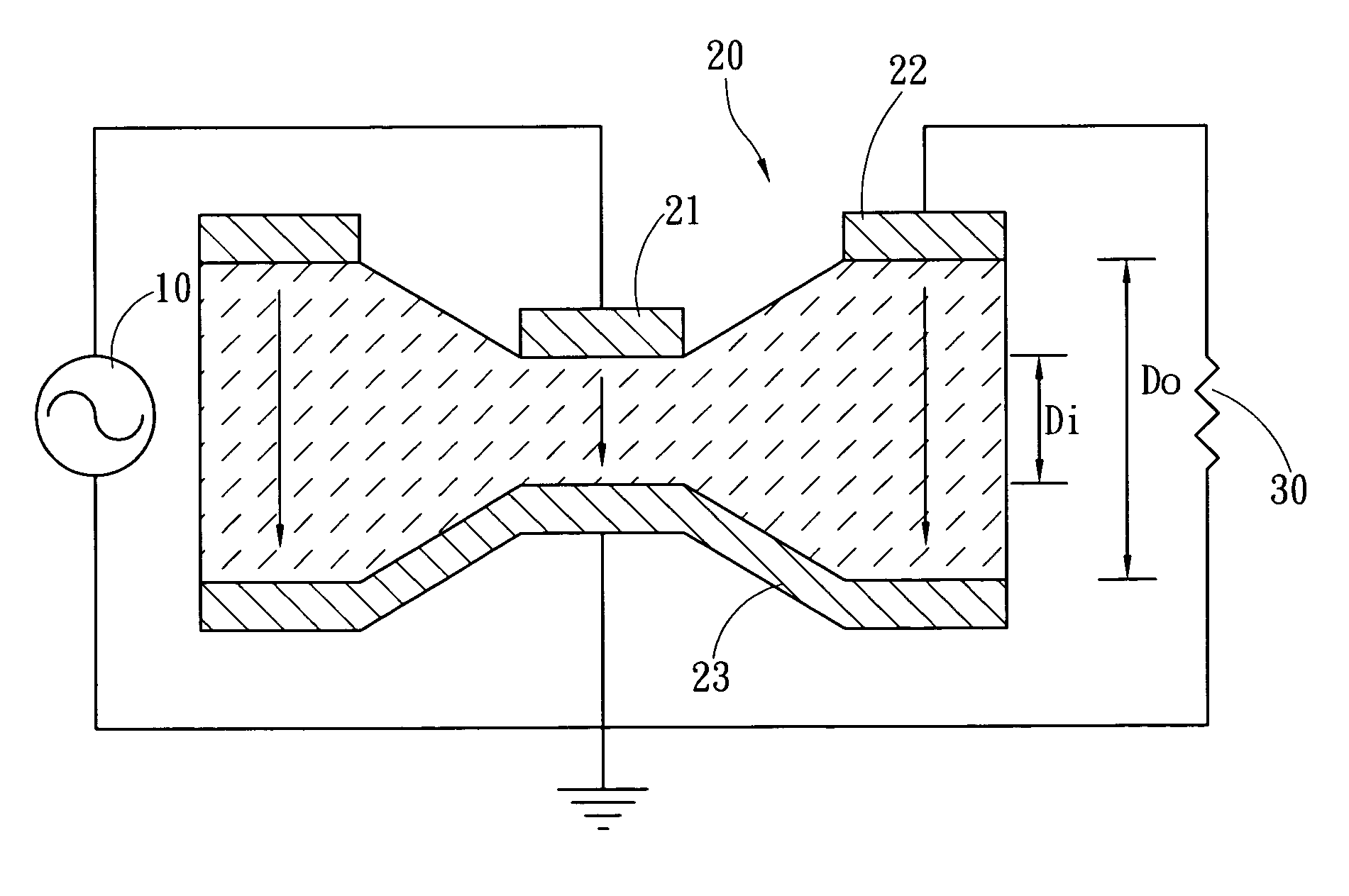
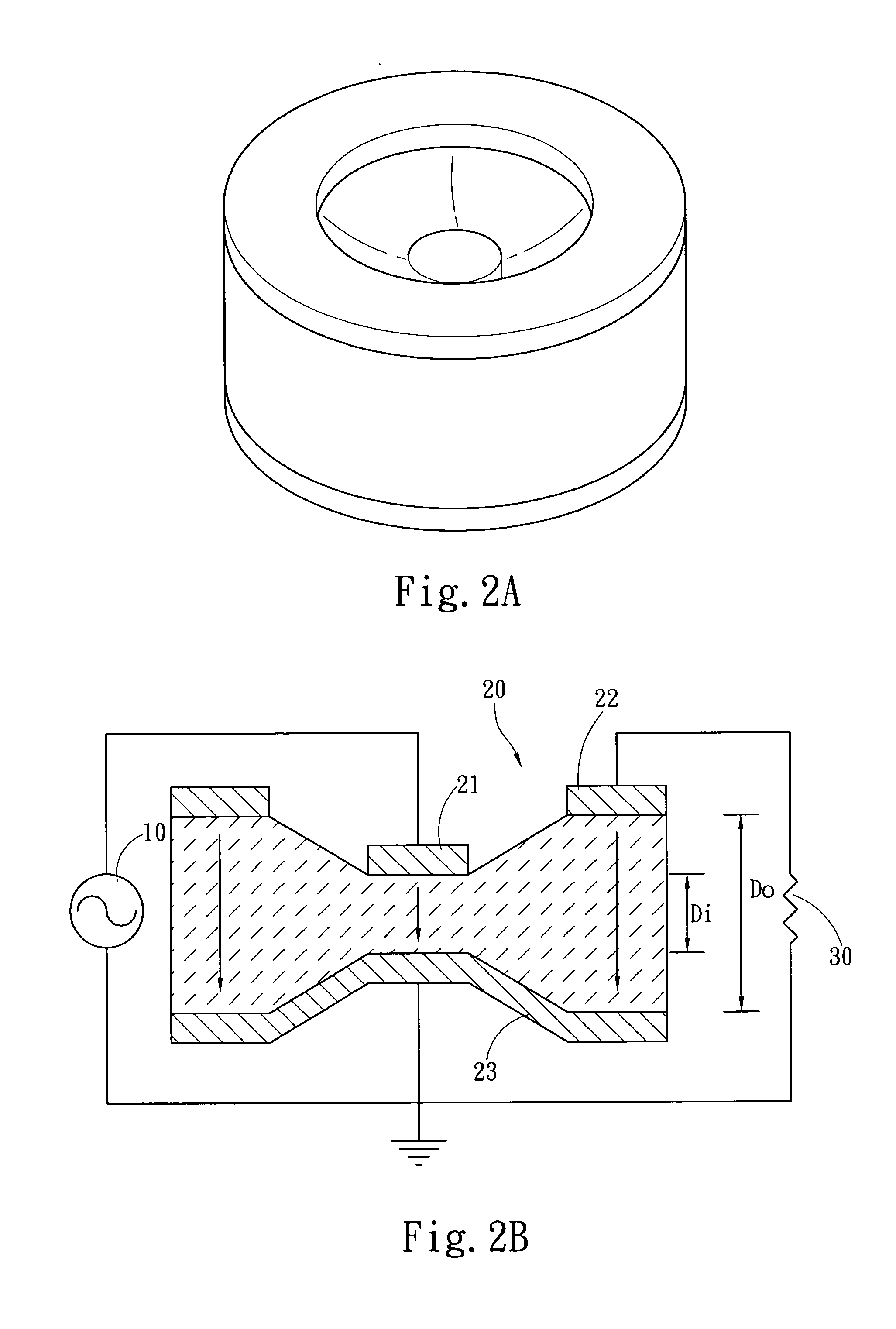
[0016]Please refer to FIGS. 2A, 2B, 3A and 3B. The piezoelectric structure 20 according to the invention is connected to a voltage source 10. The piezoelectric structure 20 has a polarized direction, an input electrode 21 electrically connected to the voltage source 10 that is normal to one of two surfaces of the polarization, and an output electric electrode 22 to output a higher or lower voltage after the piezoelectric structure 20 is activated. There is another surface other than the surface where the input and output electrodes are located that has a ground electrode 23 which is grounded. The main feature of the invention is that the distance between the input electrode 21 or the output electrode 22 and the ground electrode 23 is not equal because of the thickness of the piezoelectric plate.

[0017]According to the equation announced by Berlincourt, assumed the conventional step-up or step-down ratio is a α1, the step-up or step-down ratio of the invention is a α2, the conventiona...


PUM


Abstract

A piezoelectric structure receives input from a voltage source to generate polarization and output voltage. Two surfaces are formed on the direction normal to the polarized direction. One surface has an input electrode electrically connecting to the voltage source and an output electrode to output voltage. Another surface has a ground electrode. The distance between the input electrode and the ground electrode is different from the distance between the output electrode and the ground electrode. Through the height difference of the two electrodes, the step-up and step-down ratio can be altered.

Description

FIELD OF THE INVENTION[0001]The present invention relates to a piezoelectric structure and particularly to a piezoelectric structure that is capable of altering the step-up ratio and step-down ratio.BACKGROUND OF THE INVENTION[0002]Piezoelectricity basically is an energy transformation phenomenon between mechanical energy and electrical energy. As there is a cause and effect relationship between electric charge and strain, for an object which can generate piezoelectricity, as long as its crystal structure can generate electron dipole moment (EDM) when subject to an external force, transformation between the mechanical energy and electrical energy occurs. Then piezoelectricity can take place.[0003]Generation of EDM is caused by a special arrangement of the positive ions and negative ions inside the crystal. Different crystal lattice systems in the material can generate different EDM. The basic condition is the asymmetrical center of the crystal lattice. If there is a symmetrical cent...

Claims


Application Information

Patent Timeline
IPC IPC(8): H01L41/107
CPCH01L41/107H10N30/40
Inventor CHOU, CHIN-WENCHENG, YING-NANCHENG, YU-LIANG
Owner ZIPPY TECH
Why Eureka
Try Eureka