DC/DC converter
a converter and converter technology, applied in the direction of dc-dc conversion, power conversion system, instruments, etc., can solve the problems of uneven loss, circuit complexity, and inability to balance the electric current in the converter,
- Summary
- Abstract
- Description
- Claims
- Application Information
AI Technical Summary
Benefits of technology
Problems solved by technology
Method used
Image
Examples
first embodiment
(First Embodiment)
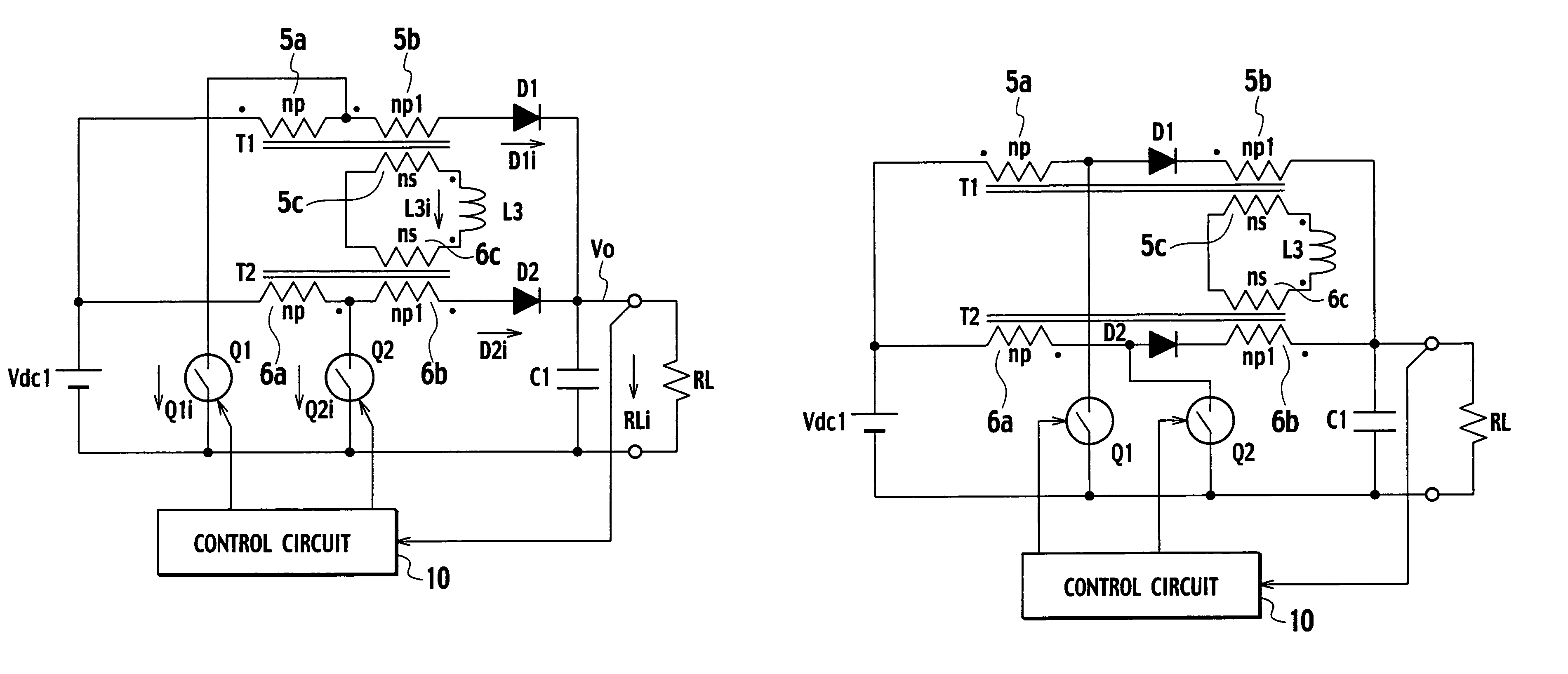
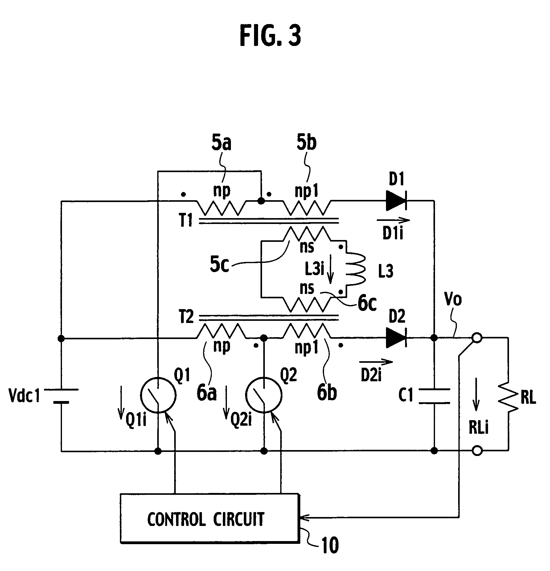
[0041]FIG. 3 is a circuit configuration diagram of a DC / DC converter of a first embodiment. The DC / DC converter shown in FIG. 3 is a converter for boosting the voltage of a DC power supply. The DC / DC converter includes the DC power supply Vdc1, a transformer T1 (corresponding to the first transformer of the present invention), a transformer T2 (corresponding to the second transformer of the present invention), a reactor L3 (corresponding to the reactor of the present invention), a switch Q1 (corresponding to the first switch of the present invention), a switch Q2 (corresponding to the second switch of the present invention), a diode D1 (corresponding to the first diode of the present invention), a diode D2 (corresponding to the second diode of the present invention), a smoothing capacitor C1, and a control circuit 10.
[0042]The transformer T1 has a primary winding 5a (np turns), an additional winding 5b (np1 turns) connected to the primary winding 5a in series, and ...
second embodiment
(Second Embodiment)
[0062]FIG. 5 is a circuit configuration diagram of a DC / DC converter of a second embodiment. The DC / DC converter shown in FIG. 5 is different from the DC / DC converter shown in FIG. 3 in the following point. That is, the diode D1 is connected between the primary winding 5a and the additional winding 5b of the transformer T1, and the diode D2 is connected between the primary winding 6a and the additional winding 6b of the transformer T2.
[0063]Since an operation of the DC / DC converter of the second embodiment thus configured is similar to that of the DC / DC converter shown in FIG. 3, similar effects can be obtained.
[0064]In addition, since the switch Q1 and the diode D1 are provided closely, and the switch Q2 and the diode D2 are provided closely, the switches Q1 and Q2 can be integrated with the diodes D1 and D2, respectively. Accordingly, the circuit can be modularized or integrated into an IC.
third embodiment
(Third Embodiment)
[0065]FIG. 6 is a circuit configuration diagram of a DC / DC converter of a third embodiment. The DC / DC converter shown in FIG. 6 is characterized in that, in the DC / DC converter shown in FIG. 3, the diode D1 is replaced with a switch Q3 (corresponding to the third switch of the present invention) comprised of a MOSFET or the like, and the diode D2 is replaced with a switch Q4 (corresponding to the fourth switch of the present invention) comprised of a MOSFET or the like.
[0066]A control circuit 10a turns on and off the switches Q1 and Q2 with a phase difference of 180°, turns on and off the switches Q3 and Q1 complementarily, and turns on and off the switches Q4 and Q2 complementarily.
[0067]Since an operation of the DC / DC converter of the third embodiment is similar to that carried out in accordance with the timing chart shown in FIG. 4, detailed description of the operation will be omitted. The timing chart of the third embodiment can be obtained by replacing the el...
PUM
 Abstract
Description
Claims
Application Information
 - R&D
- Intellectual Property
- Life Sciences
- Materials
- Tech Scout
- Unparalleled Data Quality
- Higher Quality Content
- 60% Fewer Hallucinations
Browse by: Latest US Patents, China's latest patents, Technical Efficacy Thesaurus, Application Domain, Technology Topic, Popular Technical Reports.
© 2025 PatSnap. All rights reserved.Legal|Privacy policy|Modern Slavery Act Transparency Statement|Sitemap|About US| Contact US: help@patsnap.com


