Method for inspecting a channel using a flexible sensor

a flexible sensor and channel technology, applied in the direction of fluid pressure measurement, instruments, magnetic variables, etc., can solve the problems of deformation, local variations in pressure on the sensor, lack of adhesion of the array to the surface of the material under test, etc., to facilitate the insertion of the probe and reduce the mechanical stress on the sensor associated

Inactive Publication Date: 2007-02-27
JENTEK SENSORS
View PDF15 Cites 20 Cited by
  • Summary
  • Abstract
  • Description
  • Claims
  • Application Information

AI Technical Summary

Benefits of technology

[0006]In one embodiment of the invention, the surface of an area having limited access or a channel, such as an engine disk slot, a bolt hole, or a gun barrel, is inspected by inserting a probe and flexible sensor into the channel and then translating the sensor over the material surface. The probe contains a pressurizable chamber or balloon that facilitates the insertion of the probe into the channel when deflated and holds the sensor proximate to the test material surface when inflated. The chamber is pressurized after the probe is inserted into the channel to reduce the mechanical stress on the sensor associated with the insertion into the channel. The probe may also contain a rigid support to help maintain the sensor position near the material surface. In one embodiment of the invention, the sensor is an eddy-current sensor and in another embodiment is an eddy-current sensor array.
[0007]To provide inspection co

Problems solved by technology

Typically, the defect is found when the inspection sensor, such as an eddy-current sensor, is brought into intimate contact with the surface.

Method used


Image

  • Method for inspecting a channel using a flexible sensor
  • Method for inspecting a channel using a flexible sensor
  • Method for inspecting a channel using a flexible sensor

Examples


Embodiment Construction

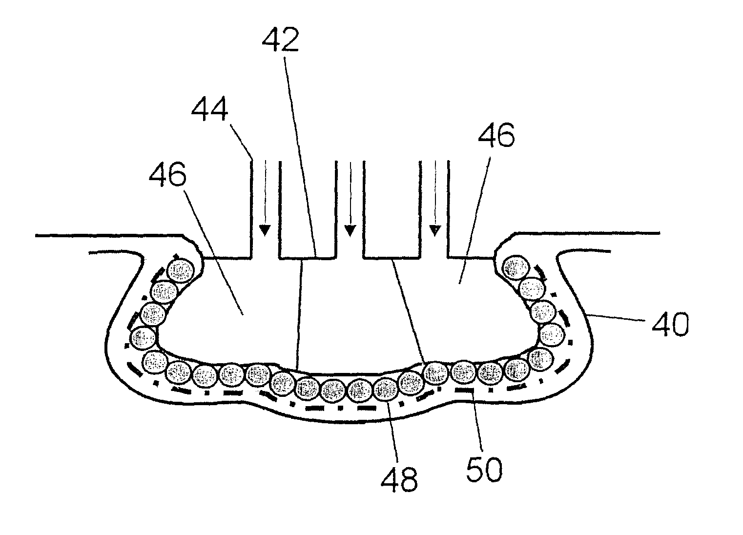
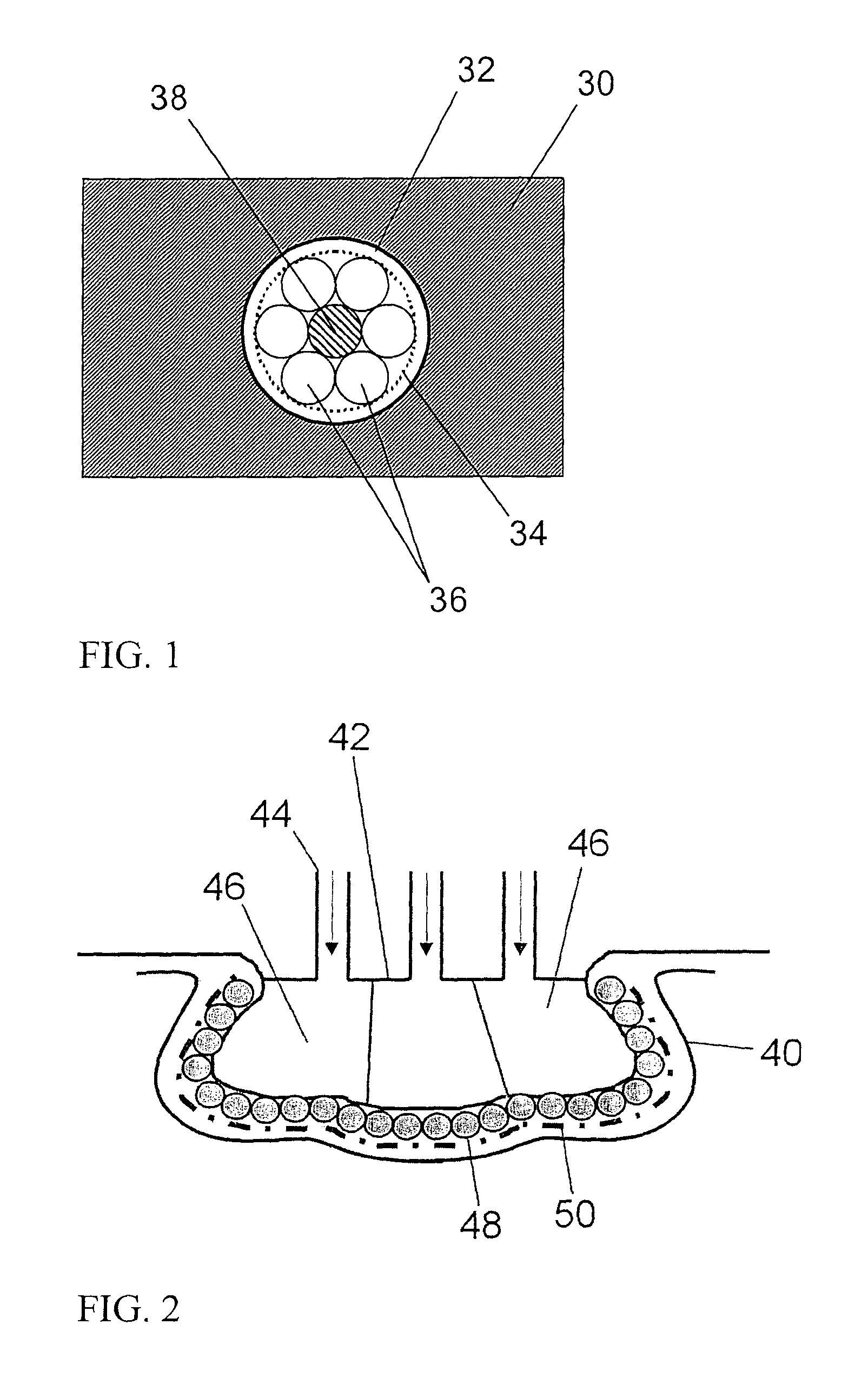
[0022]A description of preferred embodiments of the invention follows. The disclosed invention addresses the limitations of using compressible solid substrates for inspection of confined material surfaces. Probe assembly structures and methods for using these assemblies are described which provide improved inspection capabilities and extending the useful life of the sensor. The probe assemblies use fluid substrates enclosed in relatively rigid pre-shaped membrane materials or combinations of fluid filled “balloons” with compliant solids, such as foam or elastomers. Sensors placed on the surface of the shuttle are then used to inspect the material for flaws and defects or to characterize the material properties, such as coating thickness, electrical conductivity, or magnetic permeability. Detailed descriptions of these “balloon” probes are provided in U.S. patent application Ser. No. 10 / 348,339, filed Jan. 21, 2003, the entire teachings of which are incorporated herein by reference.

[...


PUM


Abstract

Described are methods for pressurizing elastic support structures or balloons in sensor probes used for the inspection of components having areas of limited access. When inflated, the balloons press flexible sensors against the surface of the material under test. When deflated, the balloons permit easier insertion of the probes into the component and reduce the mechanical stresses on the sensors, thereby extending the sensor lifetime. By sequentially partially inserting the sensor into a limited access area from either side of the limited access area and scanning in opposite directions, the entire surface of the test material can be inspected.

Description

RELATED APPLICATIONS[0001]This application is a continuation-in-part of U.S. application Ser. No. 10 / 348,339, filed Jan. 21, 2003, now U.S. Pat. No. 6,798,198 which is a continuation of U.S. application Ser. No. 10 / 172,834, filed Jun. 13, 2002, now abandoned which claims the benefit of U.S. Provisional Application No. 60 / 297,841, filed Jun. 13, 2001, and is a continuation-in-part of U.S. application Ser. No. 10 / 102,606, filed Mar. 19, 2002, now abandoned which is a continuation of U.S. application Ser. No. 09 / 946,146, filed Sep. 4, 2001, now abandoned which claims the benefit of U.S. Provisional Application No. 60 / 231,776, filed on Sep. 12, 2000, and claims the benefit of U.S. Provisional Application No. 60 / 407,436, filed Aug. 29, 2002. The entire teachings of the above applications are incorporated herein by reference.BACKGROUND OF THE INVENTION[0002]The nondestructive evaluation of materials for damage and defects often involves inspection of curved surfaces having limited access,...

Claims


Application Information

Patent Timeline
IPC IPC(8): G01N27/82G01N27/72
CPCG01N27/82
Inventor GOLDFINE, NEIL J.SCHLICKER, DARRELL E.TSUKERNIK, VLADIMIRSHAY, IAN C.GRUNDY, DAVID C.WASHABAUGH, ANDREW P.
Owner JENTEK SENSORS
Why Eureka
Try Eureka