PIR motion sensor utilizing sum and difference sensor signals

a motion sensor and sum and difference technology, applied in the field of motion sensors, can solve the problems of low accuracy of motion sensors, and high cost of cameras, and achieve the effect of reducing the probability of motion

Inactive Publication Date: 2007-02-27
SUREN SYST
View PDF13 Cites 31 Cited by
  • Summary
  • Abstract
  • Description
  • Claims
  • Application Information

AI Technical Summary

Benefits of technology

[0010]In the invention's first aspect, the improved sensor's opto-electronic system produces signals of two different frequencies in response to human motion. The system produces only single-frequency signals, however, in response to detector-interfering stimuli such as white light, shock, temperature change, radio-frequency electromagnetic radiation, etc. Signals are sent to the sensor's signal processing system, which uses the presence or absence of two frequencies to discriminate between moving objects and non-moving interfering stimuli. Thus, the improved sensor has a lower probability of indicating motion that is not in response to a moving object, but to an interfering stimulus. This would be called a “false alarm” in the case of motion sensors used to detect human intruders. Moreover, the sensor can determine direction of motion by evaluating waveform peak juxtapositions between the two different-frequency signals so that the sensor can be used, for example, to open a door only if a human is approaching it from a particular direction.
[0011]In the invention's second aspect, the improved sensor's opto-electronic system produces multiple signals from a two-dimensional array of sub-volumes within the space monitored by the sensor. The sensor's signal processing system uses those signals as information regarding size of the moving target, facilitating rejection of signals due to non-human (e.g. small animal) motion. If desired, both aspects can be combined to yield a sensor improved in all three areas mentioned.

Problems solved by technology

However, such cameras are expensive.
Because the detectors can be a significant part of the cost (5–10%) of a typical PIR motion sensor, most PIR motion sensors employ only one or two such detectors.
While effective, it happens that simple PIR sensors using a minimal number of detectors can generate false alarms from time to time, due, for example, to incident radiation of wavelength outside of the 8–14 micron band.
Such false alarms may nonetheless precipitate unneeded responses by, e.g., security personnel.

Method used


Image

  • PIR motion sensor utilizing sum and difference sensor signals
  • PIR motion sensor utilizing sum and difference sensor signals
  • PIR motion sensor utilizing sum and difference sensor signals

Examples


Embodiment Construction

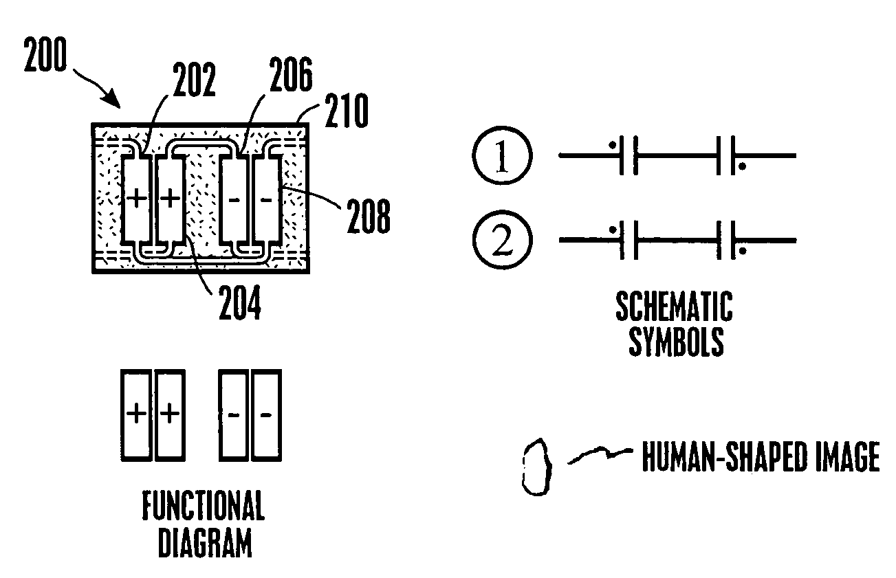
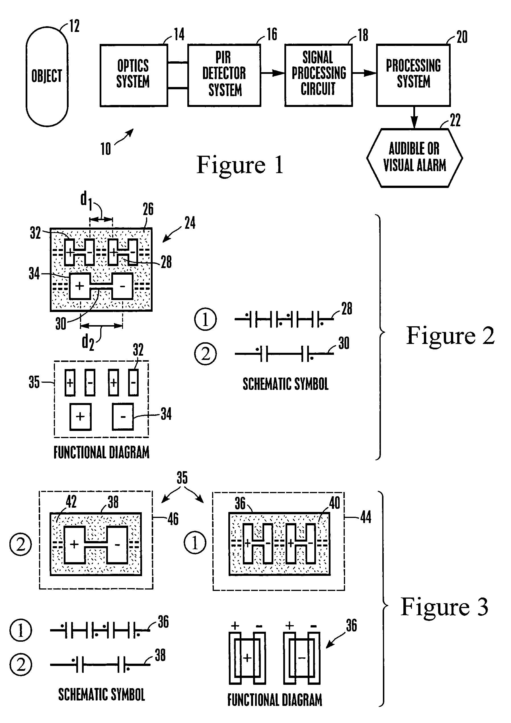
[0045]Referring initially to FIG. 1, a system is shown, generally designated 10, for detecting a moving object 12, such as a human. The system 10 includes an optics system 14 that can include appropriate mirrors, lenses, and other components known in the art for focussing images of the object 12 onto a passive infrared (PIR) detector system 16. The disclosure below discusses various embodiments of the PIR detector system 16. In response to the moving object 12, the PIR detector system 16 generates a signal that can be filtered, amplified, and digitized by a signal processing circuit 18, with a processing system 20 (such as, e.g., a computer or application specific integrated circuit) receiving the signal and determining whether to activate an audible or visual alarm 22 or other output device such as an activation system for a door, etc. in accordance with the flow charts herein.

[0046]Having described the overall system architecture, reference is now made to FIG. 2, which shows a fir...


PUM


Abstract

A passive infrared sensor has two detector elements, each of which has a positive part and a negative part, with each detector element generating respective first and second signals. The signals are added together to render a “sum” signal and are also subtracted one from the other to render a “difference” signal, and a moving object is indicated only when the “sum” signal has a frequency different than the frequency of the “difference” signal.

Description

PRIORITY CLAIM[0001]This is a continuation-in-part of and claims priority from U.S. patent application Ser. Nos. 10 / 388,862, filed Mar. 14, 2003 and 10 / 600,314, filed Jun. 20, 2003. Priority is also claimed from U.S. provisional application Ser. No. 60 / 560,228, filed Apr. 6, 2004.I. FIELD OF THE INVENTION[0002]The present invention relates generally to motion sensors.II. BACKGROUND OF THE INVENTION[0003]Motion sensors are used in security systems to detect movement in a monitored space. One type of sensor is a passive infrared (PIR) motion sensor, which detects changes in far infrared radiation (8–14 micron wavelength) due to temperature differences between an object (e.g. a human) and its background environment. Upon detection, motion sensors generally transmit an indication to a host system, which may in turn activate an intrusion “alarm”, change room lighting, open a door, or perform some other function.[0004]One way to provide motion sensing capabilities is to provide an infrare...

Claims


Application Information

Patent Timeline
Patent Type & Authority Patents(United States)
IPC IPC(8): G08B13/08G08B13/19G08B29/18
CPCG08B13/19G08B29/24G08B29/183
Inventor MICKO, ERIC SCOTT
Owner SUREN SYST
Why Eureka
Try Eureka