Using render bin parallelism for rendering scene graph based graphics data

a technology of scene graph and graphics data, applied in the field of computer graphics, can solve the problems of increasing the complexity and amount of data being sent to the display device, affecting the display effect, and incorporating graphics processors with a great deal of processing power,

Inactive Publication Date: 2007-02-27
ORACLE INT CORP
View PDF14 Cites 16 Cited by
  • Summary
  • Abstract
  • Description
  • Claims
  • Application Information

AI Technical Summary

Benefits of technology

[0013]In one embodiment, the system may be configured to utilize a scene graph directly. In another embodiment, the system may be configured to utilize a scene graph as a source for ancillary structures. The ancillary structures may aid the system in rendering and executing the scene-graph-based program. The system may also include support for messaging between threads and objects, messaging with time and / or event stamps, epochs to ensure consistency, and ancillary structures such as render-bins, geometry structures, and rendering environment structures.
[0015]One of the parallel structures created is preferably a render bin that is configured to receive and store references to particular geometry data that is to be rendered in the render bin. The render bin may have one or more render threads associated with it, thereby enabling parallel rendering utilizing multiple processors.
[0018]In some embodiments, render molecules may be used to group together objects in the scene graph that have similar properties. For example, in a scene with hundreds of objects, different subsets of the objects may share the same texture maps. These objects may be grouped together in a render molecule to reduce the amount of context switching that takes place. A render molecule is an object that defines the rest of the attribute settings for the geometries it contains. The attribute settings can include settings such as materials settings, the composite transform from the root of the scene graph to the objects contained in the render molecule. When an object is added to the scene graph it may be examined and added to a render molecule with other objects that share one or more common attributes. The objects with common attributes may then be rendered one after the other to reduce state changes.
[0019]In some embodiments, the grouped objects that form the render molecule may be named, e.g., with a tag, pointer, or handle). This way, they molecules may be reused without having to retransmit them again. This may also work well in implementations that support multiple viewer environments because each viewer can have its own render bin with a different order of molecules. Render atoms may be used to add a level of indirection in the scene graph. Advantageously, this additional level of indirection may allow ordering for more efficient rendering.
[0020]In some embodiments, parallelisms in the render bin may be utilized to improve rendering performance. Parallel rendering is desirable in some embodiments because it allows scalability. Depending on the implementation, a number of different techniques may be used to implement parallel rendering. For example, in one method, multiple renderer threads are used to draw a single canvas in parallel. However, in this method it may be necessary to guarantee that opaque objects render before transparent ones. It may also be necessary to grant each renderer thread its own context, which may drive up memory requirements.
[0022]A third method for parallel rendering, renders multiple canvases in parallel, as long as each canvas resides on a separate graphics device. In a three-screen virtual portal, for example, the system would render the three canvases (the left, the center, and the right) in parallel, since each has its own graphics device. Another constraint that may be imposed for parallel rendering is to issue swap buffer commands on all canvases associated with a single View as close in time to one another as possible. To help endure this, Java 3D will schedule parallel renderer threads only if the associated canvases share the same View. This helps to ensure that the renderer threads will be better aligned for the multiple swap buffer command.

Problems solved by technology

Modern graphics systems, however, incorporate graphics processors with a great deal of processing power.
This change is due to the recent increase in both the complexity and amount of data being sent to the display device.
Similarly, the images displayed are now more complex and may involve advanced techniques such as anti-aliasing and texture mapping.
As a result, without considerable processing power in the graphics system, the CPU would spend a great deal of time performing graphics calculations.
This could rob the computer system of the processing power needed for performing other tasks associated with program execution and thereby dramatically reduce overall system performance.
While graphics API have been successful in allowing programmers to rapidly develop graphical applications, the recent increase in the complexity of the scenes being rendered is placing ever greater demands on the CPUs and graphics systems that are executing the applications.
However, typical graphics APIs are not well suited to allow parallel processing, particularly over a network.

Method used


Image

  • Using render bin parallelism for rendering scene graph based graphics data
  • Using render bin parallelism for rendering scene graph based graphics data
  • Using render bin parallelism for rendering scene graph based graphics data

Examples


Embodiment Construction

Computer System—FIG. 1

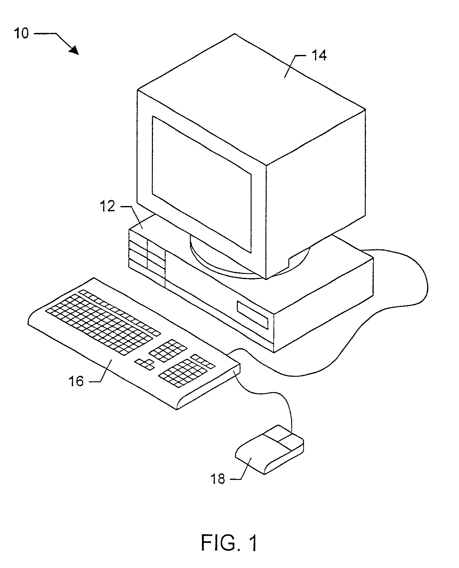
[0036]Referring now to FIG. 1, one embodiment of a computer system 10 that may used to implement the system and method described above is illustrated. The computer system may be used as the basis for any number of various systems, including a traditional desktop personal computer, a laptop computer, a network PC, an Internet appliance, a television, including HDTV systems and interactive television systems, personal digital assistants (PDAs), and other device which displays 2D and or 3D graphics.

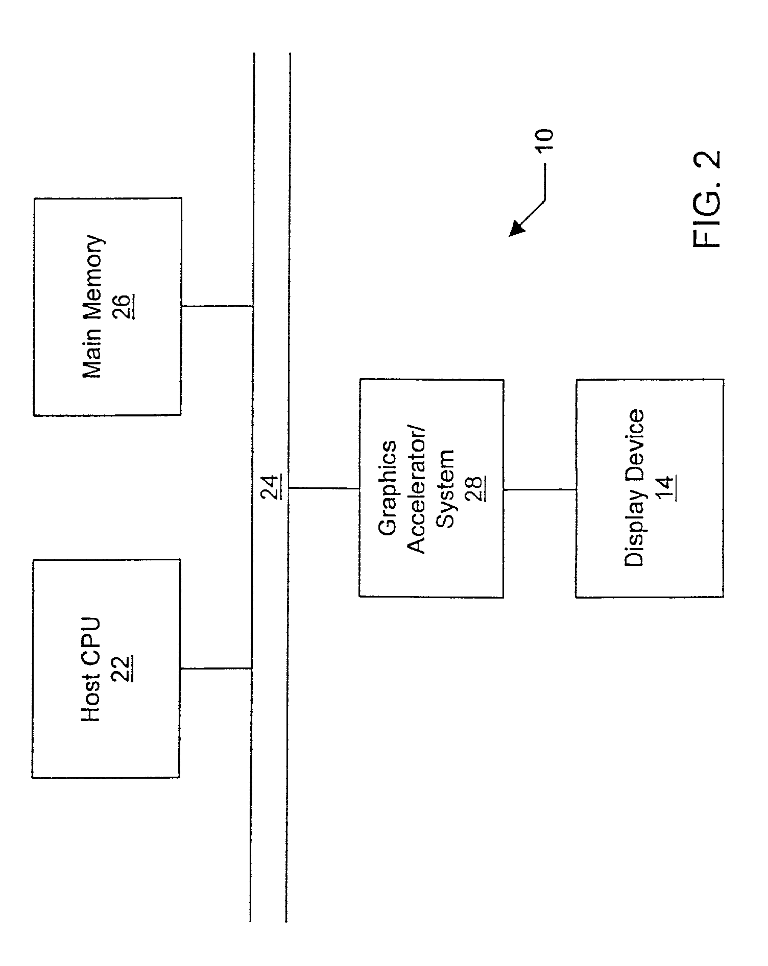
[0037]As shown in the figure, computer system 10 comprises a system unit 12 and a video monitor or display device 14 coupled to the system unit 12. The display device 14 may be any of various types of display monitors or devices (e.g., a CRT, LCD, or gas-plasma display). Various input devices may be connected to the computer system, including a keyboard 16 and / or a mouse 18, or other input device (e.g., a trackball, digitizer, tablet, six-degree of freedom input device,...


PUM


Abstract

A system and method for rapid processing of scene-graph-based data and / or programs using a render bin is disclosed. In one embodiment, the system may be configured to generate a plurality of structures and thread that manage the data originally received as part of the scene graph. The structures and threads may be configured to convey information about state changes through the use of messaging. The system may include support for messaging between threads, messaging with time and / or event stamps, epochs to ensure consistency, and ancillary structures such as render-bins, geometry structures, and rendering environment structures. One of the structures may be a render bin that may be used to implement parallel rendering.

Description

CROSS REFERENCE TO RELATED APPLICATIONS[0001]This application claims the benefit of U.S. Provisional Application No. 60 / 175,580, filed on Jan. 11, 2000, which is incorporated herein by reference in its entirety.[0002]This application is a continuation-in-part of U.S. Application Ser. No. 09 / 668,493 filed on Sep. 22, 2000, now U.S. Pat. No. 6,570,564 which claims the benefit of U.S. Provisional Application No. 60 / 156,054 filed on Sep. 24, 1999.BACKGROUND OF THE INVENTION[0003]1. Field of the Invention[0004]This invention relates generally to the field of computer graphics and, more particularly, to graphics systems and software that manage and render three-dimensional graphics data.[0005]2. Description of the Related Art[0006]A computer system typically relies upon its graphics system for producing visual output on the computer screen or display device. Early graphics systems were only responsible for taking what the processor produced as output and displaying it on the screen. In es...

Claims


Application Information

Patent Timeline
Patent Type & Authority Patents(United States)
IPC IPC(8): G06T17/00G06T15/00
CPCG06T17/005G06T15/005G06T2210/61
Inventor SOWIZRAL, HENRYRUSHFORTH, KEVINTWILLEAGER, DOUG
Owner ORACLE INT CORP
Why Eureka
Try Eureka