
Method and apparatus for image sensing with CCD

a technology of image sensing and ccd, applied in the field of ccd image sensing, can solve the problems of not being commercially achieved on a significant scal

Inactive Publication Date: 2007-02-27
FLORIDA ATLANTIC UNIVERSITY
View PDF5 Cites 52 Cited by
  • Summary
  • Abstract
  • Description
  • Claims
  • Application Information

AI Technical Summary

Benefits of technology

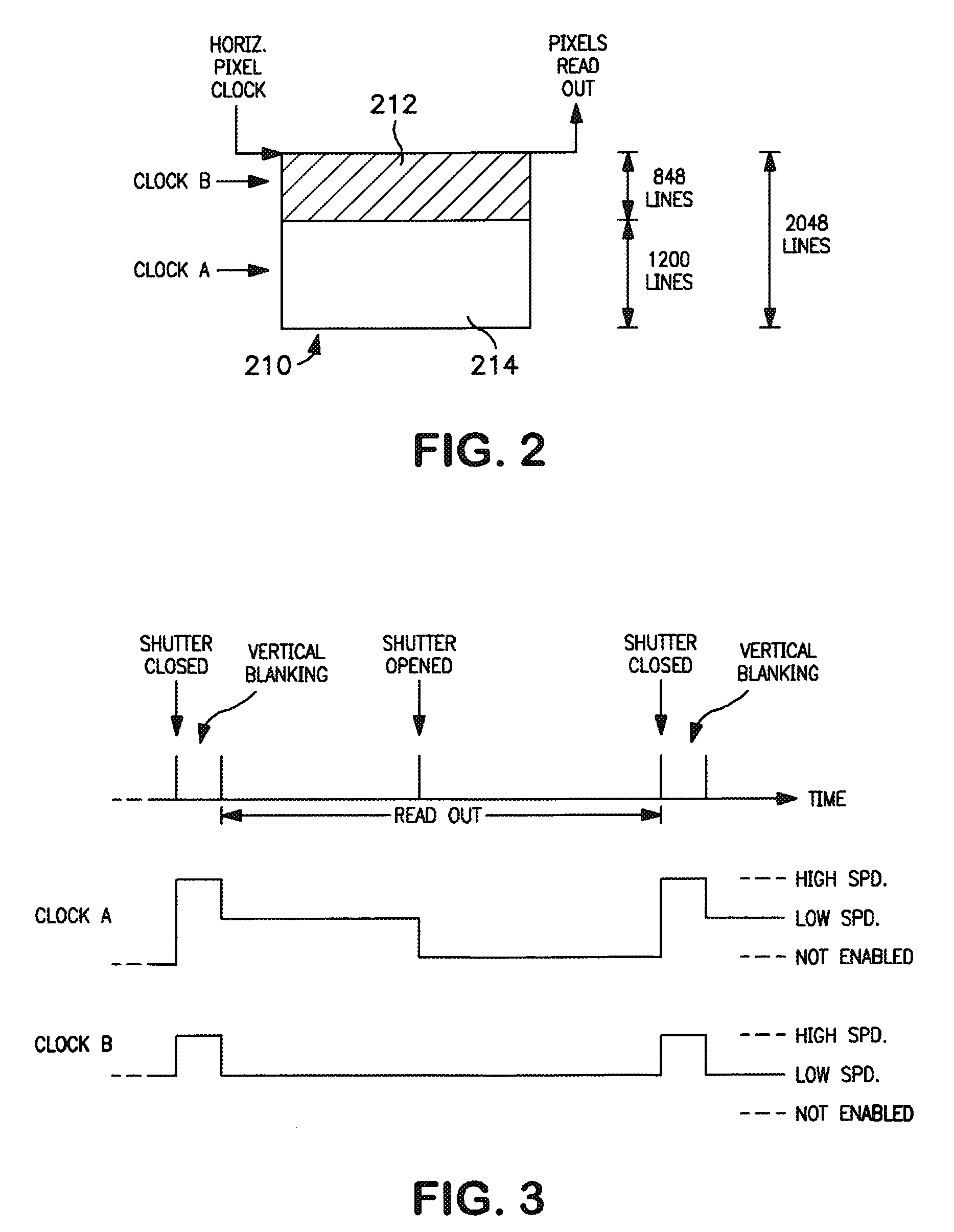
[0009]In accordance with a form of the invention, a method is set forth for producing electronic video signals representative of a focused moveable image, including the following steps: providing a charge coupled device, masking substantially less than half of the lines of the device to form a masked storage area and a substantially larger unmasked sensing area; disposing the sensing area in the path of the image; providing a shutter for periodically blocking the image from the sensing area; and providing clocking signals to the device to shift sensed lines of the image from the sensing area to the storage area and to clock image representative electronic video signals out of the device.
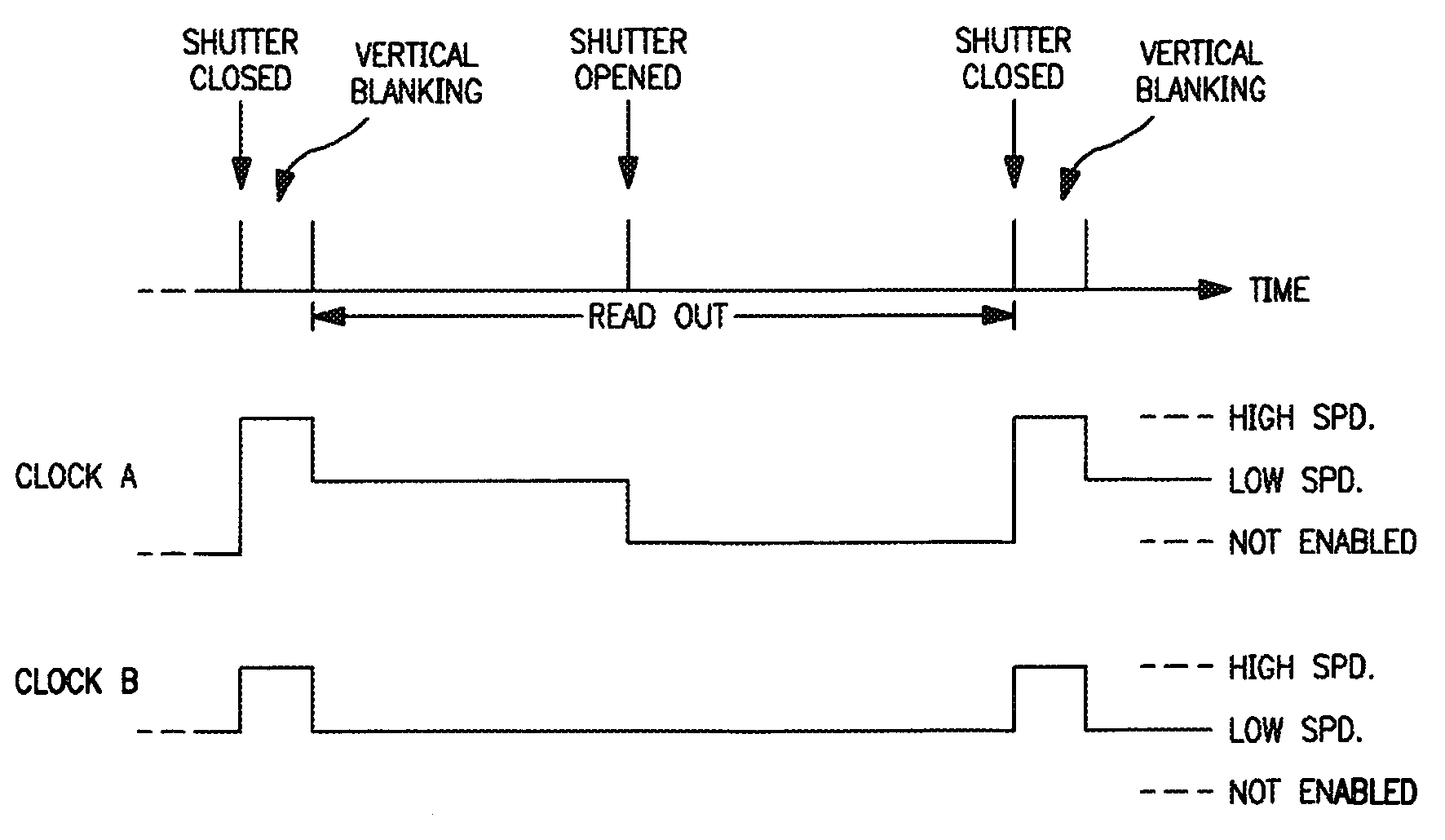
[0010]In a preferred embodiment of this form of the invention, the step of providing clocking signals to the device includes providing a first vertical clock, a second vertical clock, and a pixel rate clock. The first vertical clock is operative to shift lines in the sensing area and said second vertical clock is operative to shift lines in the storage area. In this embodiment, the substantially larger unmasked sensing area includes at least 55 percent of the lines of the device. Also in this embodiment, during a vertical blanking period after shutter closure, lines are shifted from the sensing area to fill the storage area using the first and second vertical clocks at relatively high speed and during the remainder of the shutter closure time further lines are shifted from the sensing area to the storage area and lines are shifted through the storage area and read out using the first and second vertical clocks at relatively low speed, and after shutter opening, lines in the storage area are read out using the second clock at a relatively low speed.

Problems solved by technology

It would be advantageous to have a practical electronic color video camera that could directly shoot the action to obtain color video from which good quality color motion picture film could ultimately be produced, but this has not yet been commercially achieved on a significant scale.

Method used


Image

  • Method and apparatus for image sensing with CCD
  • Method and apparatus for image sensing with CCD
  • Method and apparatus for image sensing with CCD

Examples


Embodiment Construction

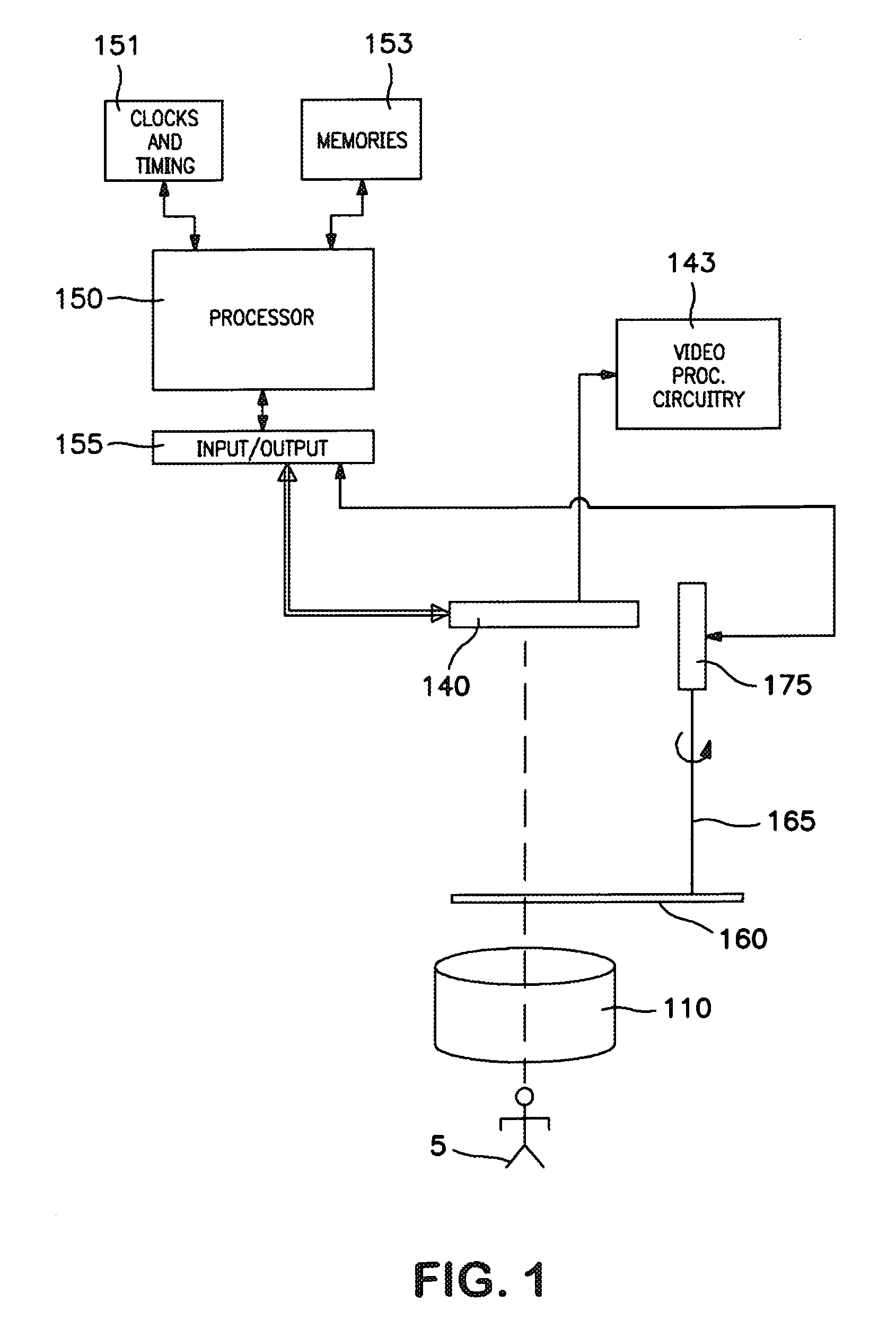
[0015]FIG. 1 shows a camera system of the general type set forth in the above referenced U.S. patent application Ser. Nos. 09 / 653,983 and 09 / 954,969. Light received from a scene 5 being viewed (typically, a moving scene) is received and focused by a lens (which can be a motion picture film camera type of lens in a form hereof) represented in the Figure by lens 110, which may be a multi-element lens or lens system. (As used herein, the term “lens” is sometimes used as convenient shorthand for a lens system.) Light focused by the lens 110 is incident on one or more CCD sensors, represented in FIG. 1 by the CCD device 140. (As described in the above-referenced copending U.S. patent applications, a beamsplitter can be used to divide light from the image between sensors used, for example, in separate luminance and color channels. The present invention has application to CCD sensors for use in these and various other types of systems, and irrespective of the number of CCD sensors employed...


PUM


Abstract

A method for producing electronic video signals representative of a focused moveable image includs the following steps: providing a charge coupled device, masking substantially less than half of the lines of the device to form a masked storage area and a substantially larger unmasked sensing area; disposing the sensing area in the path of the image; providing a shutter for periodically blocking the image from the sensing area; and providing clocking signals to the device to shift sensed lines of the image from the sensing area to the storage area and to clock image representative electronic video signals out of the device.

Description

RELATED APPLICATION[0001]The present Application claims priority U.S. Provisional Patent Application No. 60 / 271,626, filed Feb. 26, 2001, and said Provisional Application is incorporated herein by reference.FIELD OF THE INVENTION[0002]This invention relates to improvements in CCD image sensors and to application of such image sensors in a video camera system that can be utilized, for example, in an electronic cinema camera and such an electronic camera as used in motion picture film origination.BACKGROUND OF THE INVENTION[0003]Color motion pictures are often made by shooting the action with a film camera, converting the images to digital form, computer processing the digital images, and then scanning the processed images back onto film for release. It would be advantageous to have a practical electronic color video camera that could directly shoot the action to obtain color video from which good quality color motion picture film could ultimately be produced, but this has not yet bee...

Claims


Application Information

Patent Timeline
Patent Type & Authority Patents(United States)
IPC IPC(8): H04N5/335H04N9/04H04N5/217H04N5/235H04N5/351H04N5/372
CPCH04N3/1562H04N5/2353H04N5/2175H04N23/73H04N25/62
Inventor GLENN, WILLIAM E.
Owner FLORIDA ATLANTIC UNIVERSITY
Learn More