Efficient locking for thread-safe self-modifying code

a self-modification and code technology, applied in the field of computing systems, can solve the problems of significant overhead, self-modification may create errors, and the approach has a cost in the code space required to implement the specific locks for each code si

a self-modification and code technology, applied in the field of computing systems, can solve the problems of significant overhead, self-modification may create errors, and the approach has a cost in the code space required to implement the specific locks for each code si

US7185337B2Inactive Publication Date: 2007-02-27IBM CORP

Image

  • Efficient locking for thread-safe self-modifying code
  • Efficient locking for thread-safe self-modifying code

Examples


Embodiment Construction

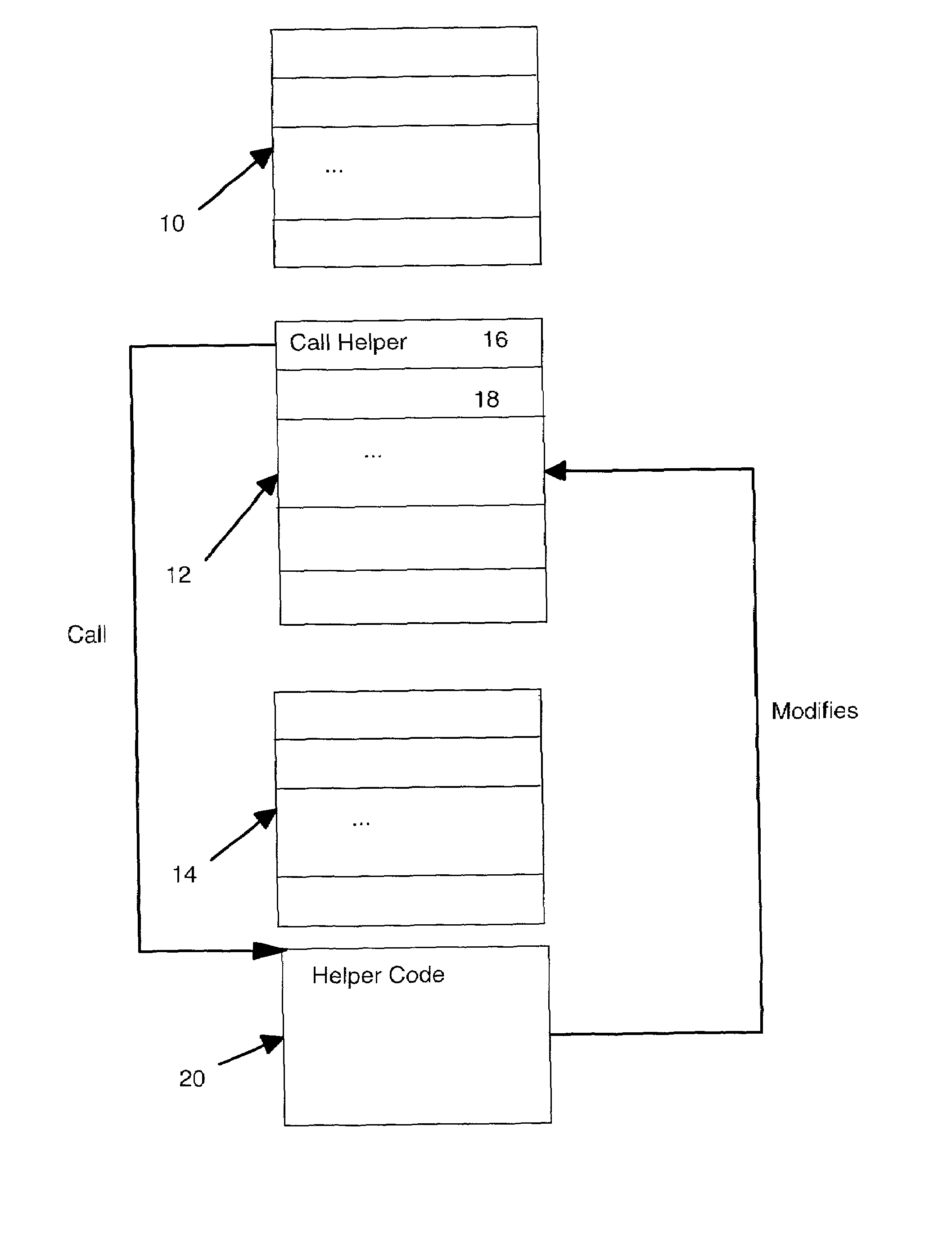
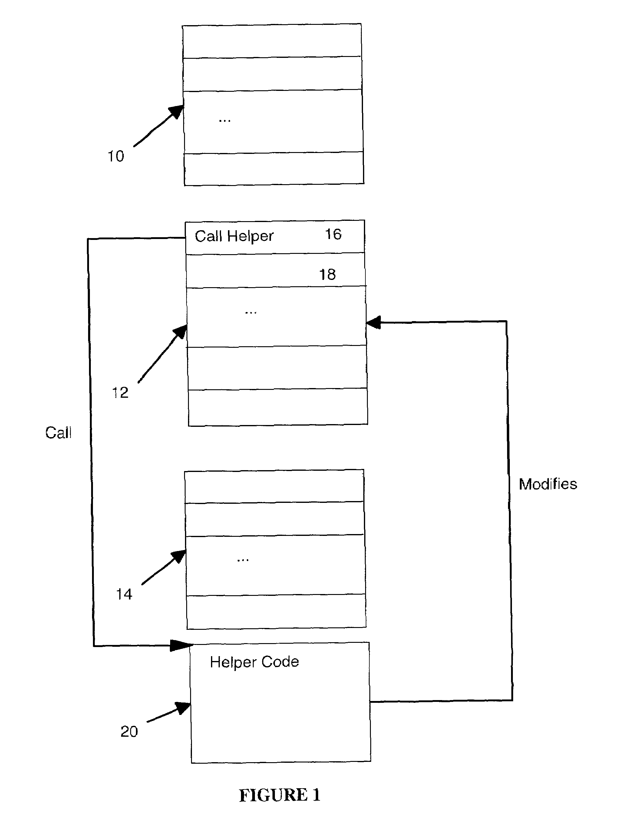
[0040]FIG. 1 shows a block diagram illustrating an example code sequence in which block 10 represents a sequence of instructions leading up to the sequence to be modified, block 12 represents the sequence of instructions to be modified, and block 14 represents instructions following the sequence to be modified. Instruction 16 within block 10 is shown in FIG. 1 to have the call to the routine which modifies block 12 instructions at runtime. Instruction 18 in FIG. 1 is the instruction following the call instruction of instruction 16. In the preferred embodiment illustrated in FIG. 1, the code to modify block 12 instruction is a reference resolving routine shown as helper code 20.

[0041]The locking mechanism of the preferred embodiment uses a compare and exchange instruction. An example of such an instruction is the cmpxchg instruction found in the instruction set for Intel Architecture x86 processors (Intel 80486-compatible processors; the instruction set is sometimes referred to as th...


PUM


Abstract

A locking mechanism for use in a multi-thread environment supporting self-modifying code in which modifications to the code are made at runtime. The locking mechanism having associated helper code accessed by a call from the first instruction address in the code block. The helper code calculating the binary encoding for the call instruction and using an atomic compare and exchange instruction to compare the calculated binary encoding with the actual contents of the first instruction address. Where there is a match, a self loop instruction is written to the first instruction address to lock the specified code block for subsequent threads. The helper code contains instructions to resolve the references in the specified block. The last such instruction is an atomic store operation to replace the self loop instruction at the first instruction address with the appropriate modified instruction.

Description

FIELD OF THE INVENTION [0001]The present invention is directed to an improvement in computing systems and in particular to an improvement in locking for multiprocessor computer systems supporting thread-safe self-modifying code.BACKGROUND OF THE INVENTION [0002]Executable code for a computer may, as part of its runtime operation, carry out self-modifying operations. One common example of such self-modifying executable code is where executable code contains unresolved data or procedure references. This will occur, for example, where Java language code is dynamically compiled to produce code that calls methods and refers to data that is unresolved at compile time. One approach to permit the compiled code to be executed correctly is to resolve the previously unresolved references at the time that the code is first executed. The compiler generates executable code for calling a routine, sometimes referred to as helper code, which carries out reference resolution at runtime. The helper co...

Claims


Application Information

Patent Timeline
27 Feb 2007
Publication
US7185337B2
IPC
G06F9/455; G06F12/00; G06F13/22; G06F7/00; G06F9/00; G06F9/445; G06F9/46
CPC
G06F9/44521; G06F9/52; G06F9/30087; G06F9/3004; Y10S707/99953; Y10S707/99932
Inventors
STOODLEY, KEVIN A.; LOW, ANDREW