Modular lateral heat press machine
a heat press machine and module technology, applied in the field of heat presses, can solve the problems of inability to expand the most heat presses available today, inconvenient use, and considerable idle time spent by the operator, and achieve the effect of convenient us
- Summary
- Abstract
- Description
- Claims
- Application Information
AI Technical Summary
Benefits of technology
Problems solved by technology
Method used
Image
Examples
first embodiment
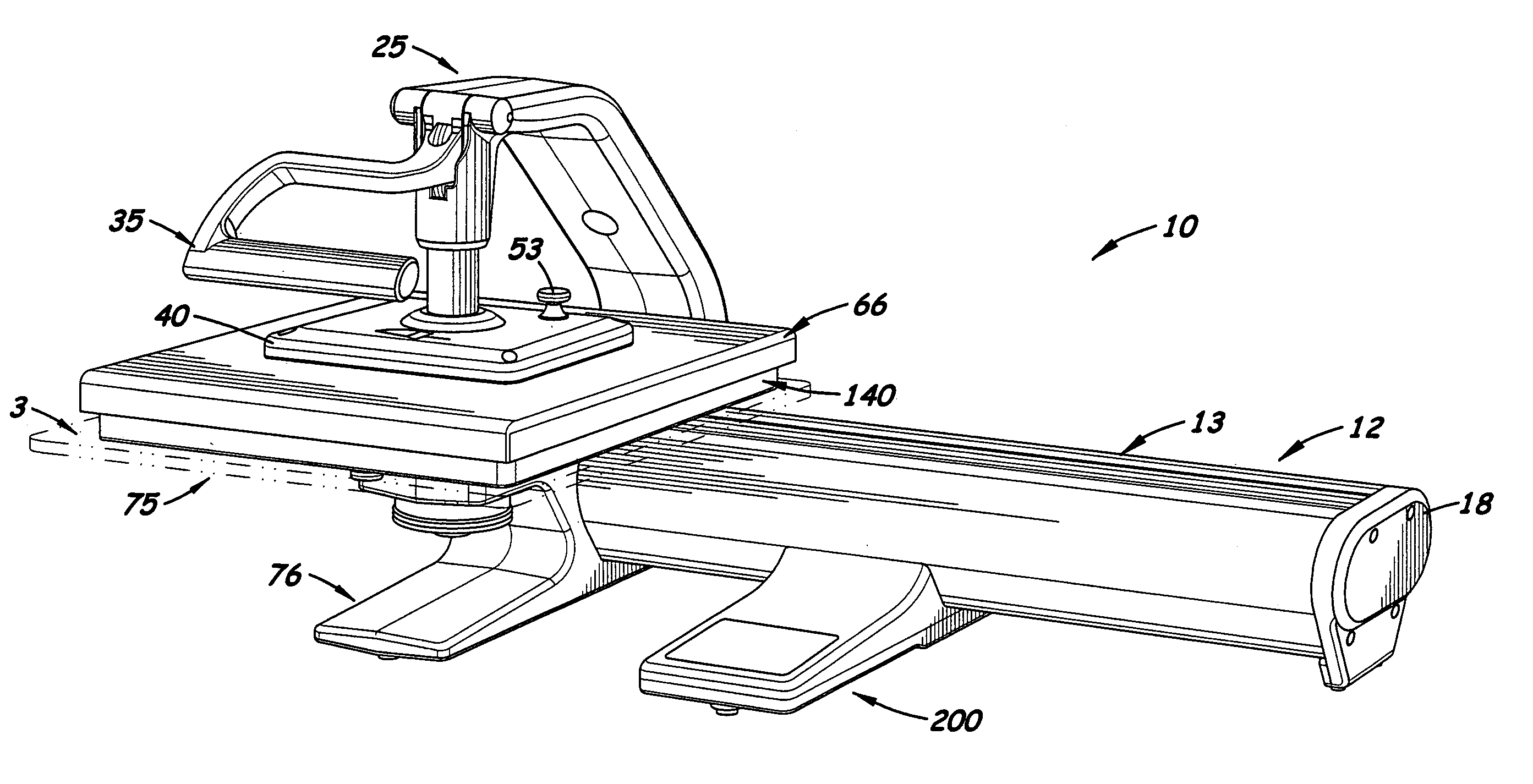
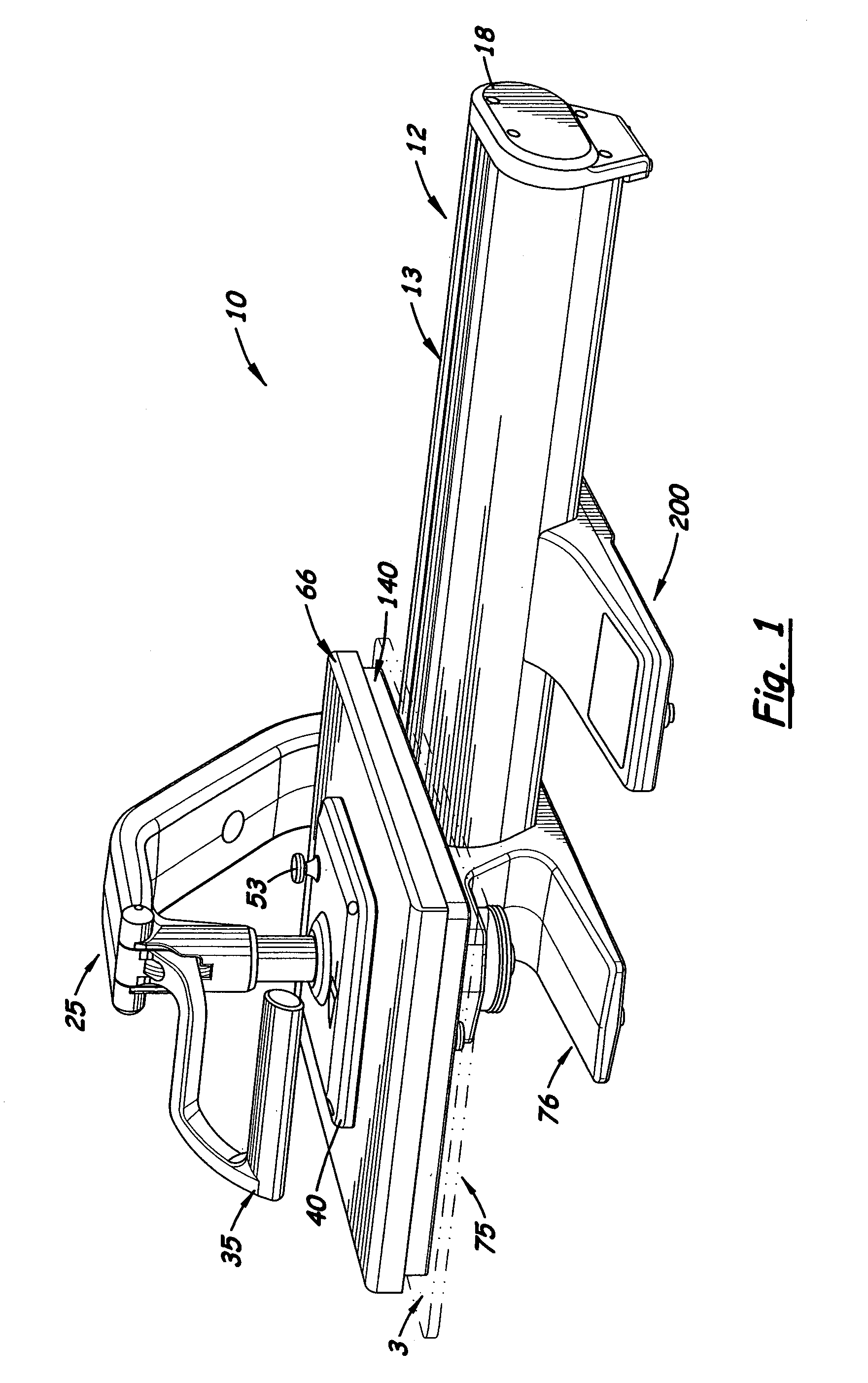
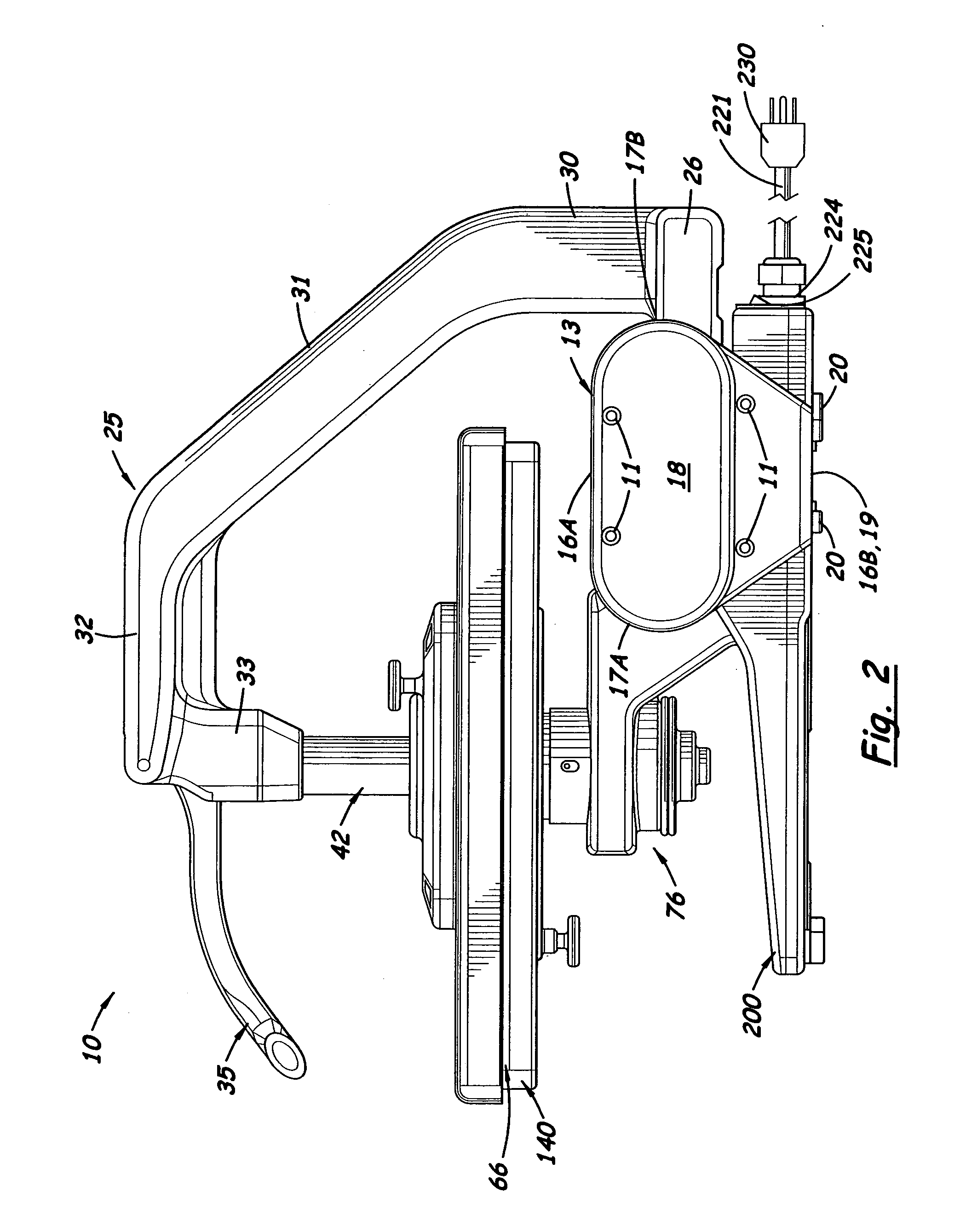
[0058]In the first embodiment shown in FIGS. 10 and 11, the lower platen 140 is a rectangular, planar structure with a flat top surface 141 and a flat bottom surface 142. Formed on the bottom surface 142 is a centrally aligned x-shaped cavity 143. The cavity 143 is made of two, intersecting small rectangular cavities 144, 145, each being complimentary in shape with the locking plate 116 used on the workstation assembly 75. By inserting the locking plate 116 into one of the two cavities 144, 145, the lower platen 140 can be aligned in either a portrait or landscape orientation, respectively. Located inside each cavity 144, 145 and near one end is a partially extending hole 146 and 146′ respectively. During assembly, the upper end of the pin 128 that extends upward from the locking plate 116 is inserted one of the holes 146 or 146′ to lock the lower platen 140 onto the locking plate 116. Formed on the bottom surface 142 of the lower platen 140 inside each cavity 144, 145 are two pairs...
second embodiment
[0059]FIGS. 12 and 13 show the lower platen 150, called a sleeve-style platen, that includes two large outer leg extensions 152, 158, respectively, and a shorter, center leg extension 153. The leg extensions 152, 153, 158 are aligned parallel and spaced apart so that one or two shirt sleeves may be placed over the top surfaces of the two outer leg extensions 152, 158. Formed on the bottom surface 154 of the center leg extension 153 is a longitudinally aligned recessed cavity 155 complimentary in shape with the locking plate 116. Also formed on the near the front edge of the cavity 155 is a partially extending hole 156 designed to receive the pin 128 on the knob assembly 126. Two complementary-shaped keyways 157, 159 are also formed inside the cavity 155 that receive the two raised nesting lugs 122, 123 on the lock plate 116.
third embodiment
[0060]FIGS. 14, 15 and 16 show the lower platen 160, called a hat-style lower platen, used to press graphics or images on the surfaces of a hat. The lower platen 160 includes an irregular-shaped body 162 with two void areas 164, 166. Formed inside each void area 164, 166 is a flat hat support surface, 168, 170 respectively. Formed centrally on the lateral edge of the body 162 is a third hat support surface 172. The top surfaces of the three hat support surfaces 168, 170, 172 are substantially level with the top surface of the body 162. Formed on the bottom surface 163 of the main body 162 is a transversely aligned recessed cavity 165. The locking plate 116 fits into the cavity 165. Formed on the front end of the recessed cavity 165 is a partially extending hole 174 designed to receive the pin 128 used to lock the lock plate 116 into the cavity 165. Also formed in the cavity 165 are two keyways 171, 173 designed to receive the two lugs 122, 123 formed on the locking plate 116.
[0061]W...
PUM
| Property | Measurement | Unit |
|---|---|---|
| Time | aaaaa | aaaaa |
| Force | aaaaa | aaaaa |
| Pressure | aaaaa | aaaaa |
Abstract
Description
Claims
Application Information
 - R&D
- Intellectual Property
- Life Sciences
- Materials
- Tech Scout
- Unparalleled Data Quality
- Higher Quality Content
- 60% Fewer Hallucinations
Browse by: Latest US Patents, China's latest patents, Technical Efficacy Thesaurus, Application Domain, Technology Topic, Popular Technical Reports.
© 2025 PatSnap. All rights reserved.Legal|Privacy policy|Modern Slavery Act Transparency Statement|Sitemap|About US| Contact US: help@patsnap.com


