Power tool

a power tool and tool body technology, applied in the field of power tools, can solve the problems of difficult attachment of fasteners, difficult to see, and cannot always be thrown onto the fitting, and achieve the effect of improving usability

Inactive Publication Date: 2007-03-06
KOKI HLDG CO LTD
View PDF21 Cites 121 Cited by
  • Summary
  • Abstract
  • Description
  • Claims
  • Application Information

AI Technical Summary

Benefits of technology

[0020]With a power tool thus constructed, the lighting angle can be fixed and held by the lighting angle adjusting and holding means after the lighting angle is adjusted. As a result, the fastener or other illuminated object can be stably illuminated without the light shaking.
[0041]With the power tool thus constructed, the index finger will not strike the light unit when the user extends the finger from the position gripping the handle grip toward the tip of the end tool because the light unit is disposed directly above the trigger. The light unit therefore does not interfere with power tool operation, and usability is improved.

Problems solved by technology

With the prior art power tool 401 described above, however, the light unit 420 is disposed externally at a position on the top of the body 410 as described above, and the light unit 420 therefore often gets in the way and makes attaching fasteners difficult.
A problem here is that because the lighting angle is fixed with such conventional power tools, light cannot always thrown onto the fitting between the bit and the head of the screw used as the fastener, or on the tip of the screw, when the bit is changed, and it becomes difficult to see.
Furthermore, because the light unit is fixed directly to the body, vibration produced when using the power tool can result in continuity failures in the light-emitting element or wiring failures.
A problem with the conventional power tool described in the Japanese Patent Application Publication No. 2001-300867, however, is that vibration produced from using the power tool causes the light from the light-emitting element to waver because the lighting angle of the light-emitting element is held by the flexible shaft, and it is difficult to see the target.
As a result, the light casts a shadow of the end tool onto the workpiece when the bit is fit into the screw head, making it difficult to see.
Furthermore, white incandescent lights are generally used for the light-emitting element in the prior art, but contrast is low and a relatively high wattage incandescent light must be used to achieve sufficient brightness.
The power supply must therefore become bulky, and this degrades operability.
Furthermore, when working in high, dimly lit places on a stepladder, for example, there is no place to set the power tool.
However, providing both a hook and a light unit on the power tool increases both the size and cost of the power tool.

Method used


Image

  • Power tool
  • Power tool
  • Power tool

Examples


first embodiment

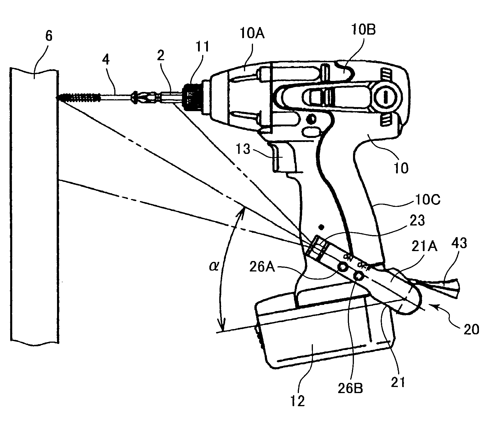
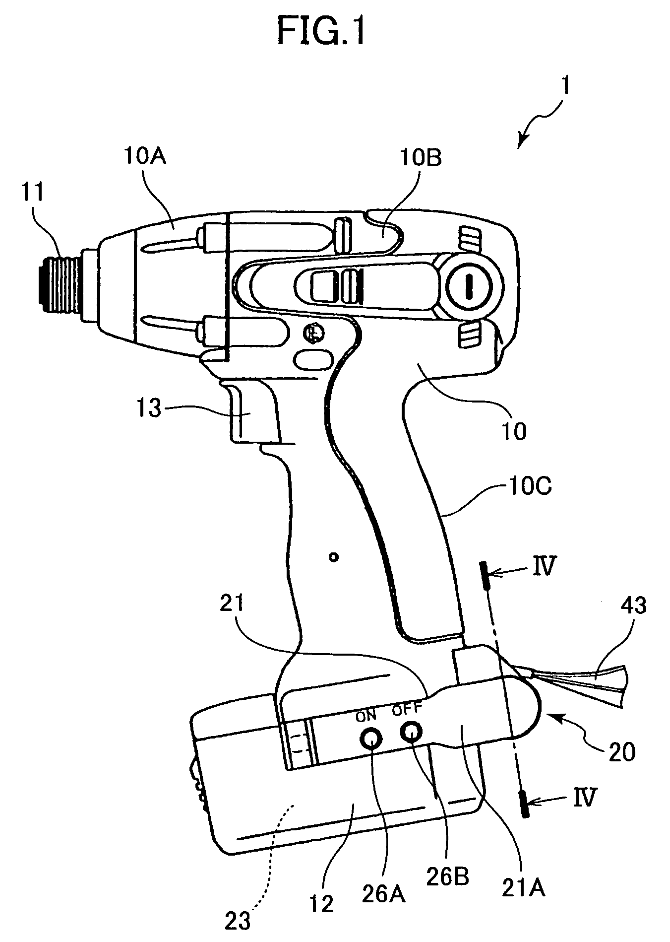
[0057]A power tool 1 according to the present invention will be described below with reference to FIG. 1 to FIG. 7. As shown in FIG. 1, this power tool 1 is specifically described as an impact driver having a generally T-shaped body 10. This body 10 includes a hammer case 10A forming the front end part of the body 10, and a housing 10B connected to the hammer case 10A and forming the back part of the body 10. A motor not shown functioning as the drive source, and mechanical parts not shown composed of, for example, a speed reduction mechanism for transferring motor torque, are housed inside the housing 10B. The speed reduction mechanism includes a planetary gear unit not shown and other parts.

[0058]An end output unit not shown is housed inside the hammer case 10A, and a chuck 11 for holding a tool or bit is disposed to the hammer case 10A. The chuck 11 has a hollow, substantially cylindrical insertion end for inserting therein a shaft-like end tool such as a bit 2, 3 (see FIG. 6 and...

fourth embodiment

[0109]In the power tool 301 according to the invention, a spray nozzle for applying a coating can be disposed in place of the light-emitting element. In this case, a spray button is disposed instead of ON switch 326A. When spraying a coating, the object to be coated, such as a bolt 304, can therefore be accurately and easily sprayed by turning the spray button on after positioning the spray nozzle close to the object to be coated.

[0110]When tightening bolts 304, for example, on a building site, it is difficult to visually determine whether the bolt 304 has been tightened. However, by spraying a coating on the bolt 304 or other fastener immediately after tightening, fasteners that have already been tightened can be recognized at a glance, and forgetting to tighten fasteners can be prevented.

[0111]A power tool according to the present invention shall not be limited to the embodiments described above, and can be modified and improved in various ways without departing from the scope of ...

second embodiment

[0113]Furthermore, the power tool of the second embodiment has three light-emitting elements and a transparent lens. Instead of this arrangement, one light-emitting element and a single donut-shaped lens can be used. The lens could be a frosted glass lens, or is formed with a fine diffraction pattern. Alternatively, luminescent paint can be impregnated in the lens. Thus, entire donut shaped lens can be lighted-up by a single light-emitting element.

INDUSTRIAL APPLICABILITY

[0114]As described above, the present invention can be widely used for tightening and loosening fasteners such as screws and bolts in the building site.


PUM

PropertyMeasurementUnit
lengthaaaaaaaaaa
distanceaaaaaaaaaa
thickaaaaaaaaaa

Abstract

A power tool has a light unit provided at the bottom part of the handle grip. The light unit can be adjusted to change the lighting angle and can hold the desired lighting angle. The light unit thus disposed does not get in the way, the lighting angle of the light unit is variable and the emitted light does not shake, depletion of the power supply due to the light switch of the light unit being left on is prevented, shadows of the end tool are not easily produced by light from the light unit, lighting contrast is high, wiring failures and continuity faults in the light-emitting element do not occur easily, and a small, economical power tool can be provided. The light-emitting element of the light unit is a yellow LED. The light unit turns off automatically at a predetermined time after the light turns on.

Description

TECHNICAL FIELD[0001]The present invention relates to a power tool that has a light for illuminating a fastener affixed to a workpiece or illuminating the bit used to drive the fastener.BACKGROUND ART[0002]Power tools used to drive a screw or other threaded fastener by way of a bit or other end tool, and having a light, are now common. When the power tool is used in a dark place, the light illuminates both the fastener being affixed to the workpiece, and the bit used to drive the fastener, thereby making it easier to use the power tool in dark places.[0003]More specifically, as shown in FIG. 14, this power tool 401 has a body 410, and inside the body 410 has a motor not shown as the drive source, and mechanical parts not shown for transferring torque from the motor not shown. An end output unit not shown is housed near the distal end inside the body 410, and a tool chuck 411 is disposed to this distal end. The tool chuck 411 is drivably linked to the end output unit not shown, and a...

Claims


Application Information

Patent Timeline
Patent Type & Authority Patents(United States)
IPC IPC(8): B25B23/18B23B45/02B25F5/00B25F5/02
CPCB25B23/18B25F5/021Y10T408/21Y10T408/96
Inventor OOMORI, KATSUHIROYOSHIMIZU, CHIKAIHARADA, HIDEKAZUTAKANO, NOBUHIRO
Owner KOKI HLDG CO LTD
Why Eureka
Try Eureka