Level difference correcting method and image pick-up device using the method

a level difference and level correction technology, applied in the field of level difference correction in black level, can solve the problems of increasing equipment temperature, reducing the quantity of saturated signals, and intense heat damage, and achieve the effect of improving the problem

Inactive Publication Date: 2007-03-06
RICOH KK
View PDF4 Cites 22 Cited by
  • Summary
  • Abstract
  • Description
  • Claims
  • Application Information

AI Technical Summary

Benefits of technology

[0011]It is an object of this invention to provide a method of and apparatus for processing method picture signal that can obtain the OB level difference at the best timing and with a minimum error, and can improve a problem occurring due to correction of the OB level difference.

Problems solved by technology

On the other hand, as small size and high speed have been achieved, temperature in the equipment increases, to thereby cause various problems.
Among these problems, characteristic deterioration due to heat is intense in the CCD image pickup device which has been widely used as an imager in a digital camera.
When the characteristic is deteriorated due to heat, there are such problems that a significant point appears due to an increase of dark current in a unit of pixel, which is referred to as temperature flaw, quantity of saturated signals decreases, and dark current on the whole image increases.
Hence, if the black level is different between the OB section and the effective pixel section, such a problem occurs that even if in a shaded state, the screen becomes bright as if light shines thereon.
Thus, if the OB level difference is not corrected, considerable deterioration occurs in the image quality.

Method used


Image

  • Level difference correcting method and image pick-up device using the method
  • Level difference correcting method and image pick-up device using the method
  • Level difference correcting method and image pick-up device using the method

Examples


Embodiment Construction

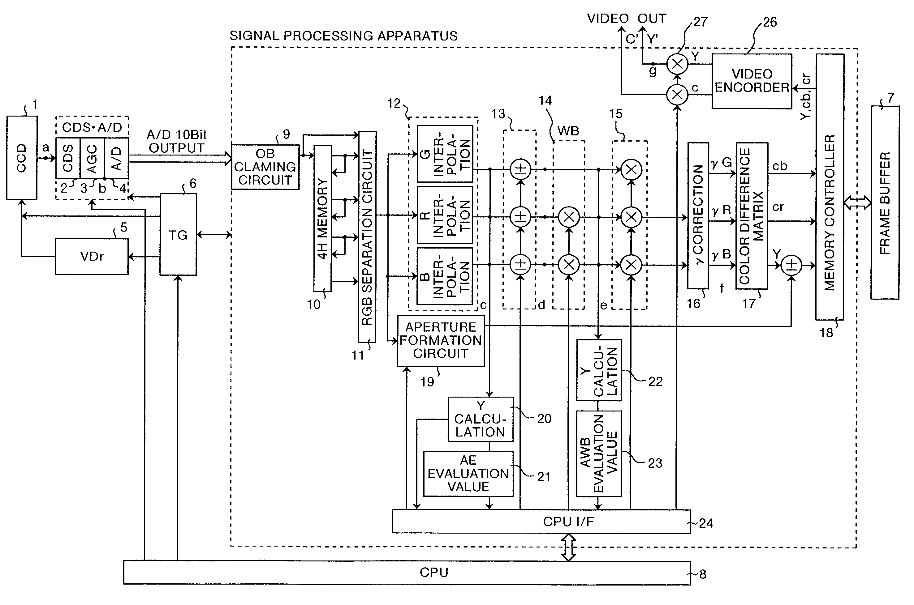
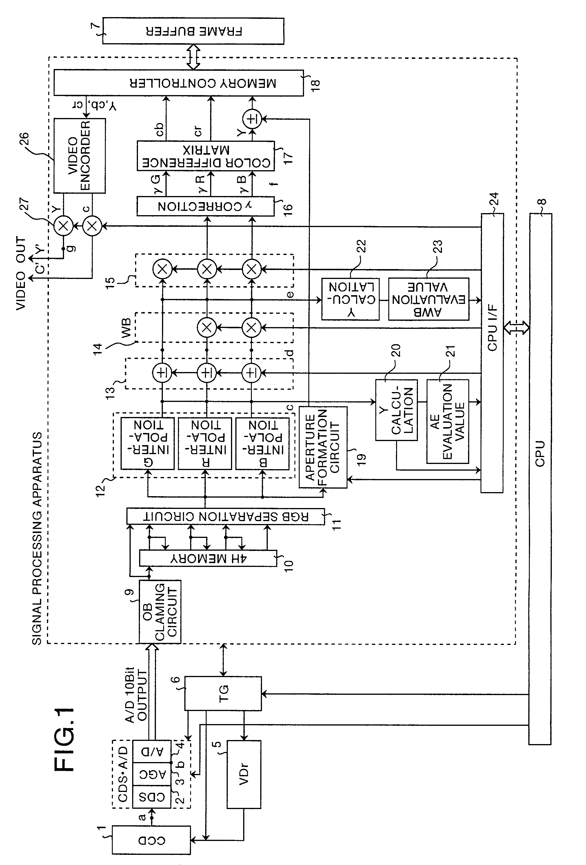
[0034]Preferred embodiments of the picture signal processing method and the picture signal processing apparatus according to the present invention will now be explained, with reference to the drawings.

[0035]FIG. 1 shows one example of a circuit for realizing the present invention. In FIG. 1, electric charge generated due to photoelectric exchange by a two-dimensional CCD image pickup device (hereinafter referred to as “CCD”) is subjected to horizontal and vertical driving pulses output from a timing generator (hereinafter referred to as “TG”) 6, and a vertical drive section (hereinafter referred to as “VDr”) 5, and carried to a correlated double sampling, analog / digital conversion section (hereinafter referred to as “CDS·A / D”. The CDS·A / D performs correlated double sampling of an output signal of a CCD1 by a CDS circuit 2, and a 10-bit digital signal which is multiplied by a predetermined gain (Gb) in an AGC amplifier circuit 3 and A / D converted in an A / D conversion section 4 is tra...


PUM


Abstract

An OB level difference is calculated from the luminance signal levels of at least two frames which are exposed for proper exposure time and for exposure time different from the proper exposure time, and the OB level difference is corrected in an input step of a signal processing circuit. Calculation of the OB level difference is performed regularly from immediately after power on of the equipment, the OB level difference obtained in each frame is multiplied, and a value obtained by dividing the multiplied OB level difference by the number of sampled frames is designated as a correction value.

Description

FIELD OF THE INVENTION[0001]The present invention relates to correction of level difference in black level, which is a difference (“OB level difference”) between an optical black level of a CCD image pickup device and a black level of a picture signal.BACKGROUND OF THE INVENTION[0002]Japanese Patent Application Laid-Open No. 5-110941 discloses a prior art. This prior art is characterized in having an output control circuit which reads out output data for each field from a photosensitive section of the CCD image pickup device through a transfer section, and reads out again output data for one line of the photosensitive section, synchronously with the first horizontal synchronizing signal after readout of the output data for each field, so that a level difference in black level can be corrected by a black level correction signal obtained for each field scan, without requiring manual adjustment.[0003]Japanese Patent Application Laid-Open No. 2000-152098 discloses another prior art. Thi...

Claims


Application Information

Patent Timeline
Patent Type & Authority Patents(United States)
IPC IPC(8): H04N9/64H04N5/243H04N5/20H04N5/335H04N5/341H04N5/361H04N5/369H04N5/3728H04N9/07H04N9/72
CPCH04N5/20H04N9/72H04N2101/00
Inventor NAKAHIRA, TOSHIAKIYOSHIDA, AKIHIRO
Owner RICOH KK
Why Eureka
Try Eureka