Optical disk device and method of adjusting tilt control amount

a technology of optical disk and tilt control, which is applied in the direction of digital signal error detection/correction, instruments, recording signal processing, etc., can solve the problems of recording or reproducing problems, tilt adjustment errors, and adjustment discrepancies

Inactive Publication Date: 2007-03-06
RICOH KK
View PDF16 Cites 7 Cited by
  • Summary
  • Abstract
  • Description
  • Claims
  • Application Information

AI Technical Summary

Benefits of technology

[0011]It is an object of the present invention to provide an optical disk device that can perform accurate tilt adjustment without being affected by zero point deviance and sensitivity scattering (fluctuation) of tilt detection means, zero point deviance and sensitivity scattering of objective lens inclining means, offset and gain scattering of a circuit, and a change of them.
[0012]It is another object of the present invention to provide a method of adjusting a tilt control amount in which accurate tilt adjustment can be performed without being affected by zero point deviance and sensitivity scattering of tilt detection means, zero point deviance and sensitivity scattering of objective lens inclining means, offset and gain scattering of a circuit, and a change of them.

Problems solved by technology

When the optical axis of the objective lens is inclined with respect to the recording surface of the optical disk, optical aberration is generated on the light spot, and as a result, a recording or reproducing problem occurs.
However, in the tilt adjustment system (that is not limited to the system using the piezoelectric element) in which the objective lens is not inclined together with the sensor, a tilt adjustment error is caused by a zero point and sensitivity of the sensor, and a zero point and a sensitivity scattering of mechanisms for inclining the objective lens.
For this reason, it is necessary to accurately adjust the position of the sensor, and the position of the mechanism for inclining the objective lens, but an adjustment discrepancy is generated due to the adjustment difference and the circuit offset.
Furthermore, the sensitivity scattering of the mechanisms that incline the sensor and the objective lens has to be suppressed as much as possible, but the extent of limitation of such suppression is limited because of the material difference and the gain difference of a detection circuit and a driving circuit.
In addition, when the sensitivity changes as time lapses, the tilt adjustment error increases.
Accordingly, in the system in which the objective lens is not inclined together with the sensor, the tilt adjustment cannot be performed adequately.

Method used


Image

  • Optical disk device and method of adjusting tilt control amount
  • Optical disk device and method of adjusting tilt control amount
  • Optical disk device and method of adjusting tilt control amount

Examples


first embodiment

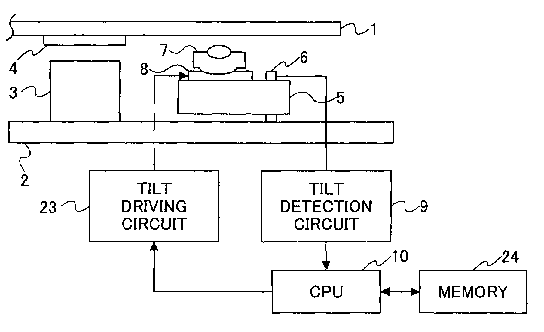
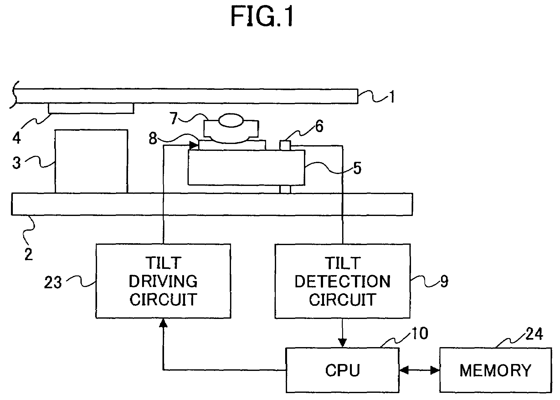
[0049]FIG. 1 shows the configuration of an optical disk device according to the present invention. In this embodiment, the optical disk device includes a chassis 2, a spindle motor 3, a turning table 4, an optical pickup 5, a tilt sensor 6, an objective lens actuator 7, a tilt adjustment mechanism 8, a tilt detection circuit 9, a CPU 10, a tilt driving circuit 23, and a memory 24.

[0050]An optical disk 1 is attached on the turning table 4 of the spindle motor 3 fixed on the chassis 2, and is rotated in this attached state. The optical pickup 5 is supported by the chassis 2 such that the optical pickup 5 is directed in the radial direction of the optical disk 1. The tilt sensor 6 is provided at the optical pickup 5. The objective lens actuator 7 is attached to the optical pickup 5 via the tilt adjustment mechanism 8 that mechanically inclines the objective lens actuator 7.

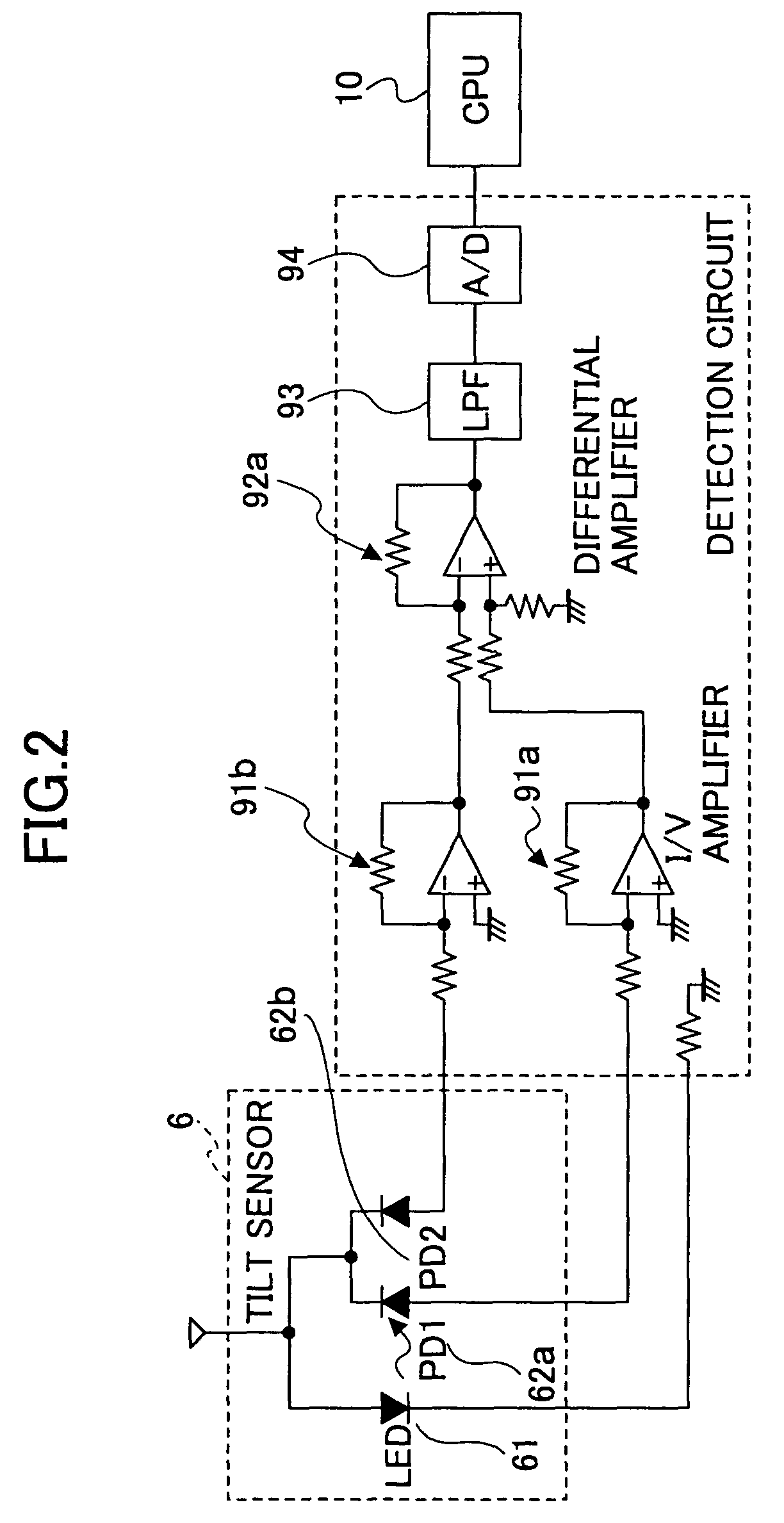
[0051]The tilt sensor 6 includes a light emitting element and two divided light receiving elements so that the lig...

second embodiment

[0078]Accordingly, with the second embodiment, the accurate tilt adjustment can be performed without being affected by the scattering in the sensitivity of the tilt sensor 6, the gain of the tilt detection circuit 9, the sensitivity of the tilt adjustment mechanism 8, and the gain of the tilt driving circuit 23.

[0079]A preferred third embodiment of the present invention will be described. In the third embodiment, the configuration of the optical disk device is the same as in the first embodiment.

[0080]According to the third embodiment, the tilt amount A and the control value B of the optical disk whose warping is larger than the predetermined amount C are not stored as they are, but the calculated value k′ is stored in the memory 24. FIG. 9 shows the flow of this operation. The processes in Steps S401 to S404 are the same as the processes in Steps S301 to S304 of the optical disk device shown in FIG. 8 in the second embodiment.

third embodiment

[0081] after the optimum tilting search process is performed in Step S404, the tilt value A and the control value B are held without being stored in the memory 24. Thereafter, the constant k′ for the tilt control is calculated at Step S406, and the value k′ is stored in the memory 24 at Step S407.

[0082]In this manner, by storing the value k′, it becomes sufficient that the CPU 10 performs the operation once at the time of the adjustment for obtaining the value k′, so that the work load and the time for the operation can be decreased, and the use amount of the memory 24 can be saved.

[0083]Next, a fourth preferred embodiment will be described. The configuration of the optical disk device is the same as in the first embodiment.

[0084]According to the fourth embodiment, the process of canceling the sensitivity change that occurs as the time lapses is performed in the optical disk device adjusted in the processes in the second or third embodiment. FIG. 10 shows the flow of the processes.

[...


PUM

PropertyMeasurementUnit
densityaaaaaaaaaa
voltagesaaaaaaaaaa
voltageaaaaaaaaaa

Abstract

In a state in which an optical disk having a warping amount equal to or smaller than a predetermined amount is attached to a spindle motor, an output of tilt detection result is stored as a reference tilt value in a memory. At this time, a control signal corresponding to a driving inclining amount in which inclining the objective lens by the driving inclining amount minimizes the inclination of the objective lens from the attached optical disk is stored as a reference control value in the memory. An CPU a multiplies difference between a detection result of the tilt detection and the reference tilt value by a control constant, and adds the reference control value to the multiplied difference, and provides the thus-obtained control signal to a tilt driving circuit.

Description

BACKGROUND OF THE INVENTION[0001]1. Field of the Invention[0002]The present invention relates to an optical disk device that writes information on an optical disk and reads information from the optical disk. Further, the present invention relates to a method of adjusting the optical disk device. Particularly, the present invention relates to an optical disk device that can perform accurate tilt adjustment without being affected by an error, and to a method of adjusting the optical disk device.[0003]2. Description of the Related Art[0004]An objective lens focuses laser light to form a light spot on a track of an optical disk in order to perform recording or reproducing. When the optical axis of the objective lens is inclined with respect to the recording surface of the optical disk, optical aberration is generated on the light spot, and as a result, a recording or reproducing problem occurs. For this reason, the inclination of the objective lens with respect to the recording surface ...

Claims


Application Information

Patent Timeline
Patent Type & Authority Patents(United States)
IPC IPC(8): G11B7/00G11B7/095
CPCG11B7/0956
Inventor OHNO, TAKEHIDEAOTA, YOSHIAKI
Owner RICOH KK
Why Eureka
Try Eureka