
Conditioning roller drive

a technology of roller drive and roller blade, which is applied in the field of conditioning roller drive, can solve the problems of increasing cost, cracking of the waxy surface of the crop stem, and high cost of gear box arrangement,

Active Publication Date: 2007-03-13
MACDON INDS
View PDF10 Cites 26 Cited by
  • Summary
  • Abstract
  • Description
  • Claims
  • Application Information

AI Technical Summary

Benefits of technology

The present invention provides an improved arrangement of conditioning rollers for a harvester. The arrangement includes two rollers that are mounted in parallel relationship and can move relative to each other. The rollers have flutes that are angled outwardly and extend along their axes. The mounting assembly allows for relative movement of the rollers in a way that changes the spacing between their flutes. The rollers are driven by a common shaft and a drive timing device ensures accurate timing between the rollers. The arrangement can be used in systems where both rollers are independently driven or only one roller is driven. A spring applies force to the second roller through a link pivoted about a pivot axis. The drive transfer assembly includes gear wheels and idler gears to transfer rotation from one roller to the other. The first and second arms are linked for pivotal movement about the third and fourth idler wheels, and the arms are constrained to move symmetrically relative to an imaginary center line. The technical effects of the invention include improved conditioning of crop material, reduced wear on the rollers, and improved timing accuracy between the rollers.

Problems solved by technology

The intermeshing of the flutes causes the crop material to be bent as it passes between the rollers causing a cracking of the waxy surface of the crop stem.
The gear box arrangement is expensive and is of relatively wide width.
This arrangement is highly complex involving a high number of idler sprockets thus increasing cost and increasing chain wear.
At the same time, the amount of space available is limited by the geometry of the supporting machine, and in some designs the conditioner is located between two spaced support legs of the frame of the machine which are set at a distance which cannot readily be changed.
This arrangement has not proven to be successful.

Method used


Image

  • Conditioning roller drive
  • Conditioning roller drive
  • Conditioning roller drive

Examples


Embodiment Construction

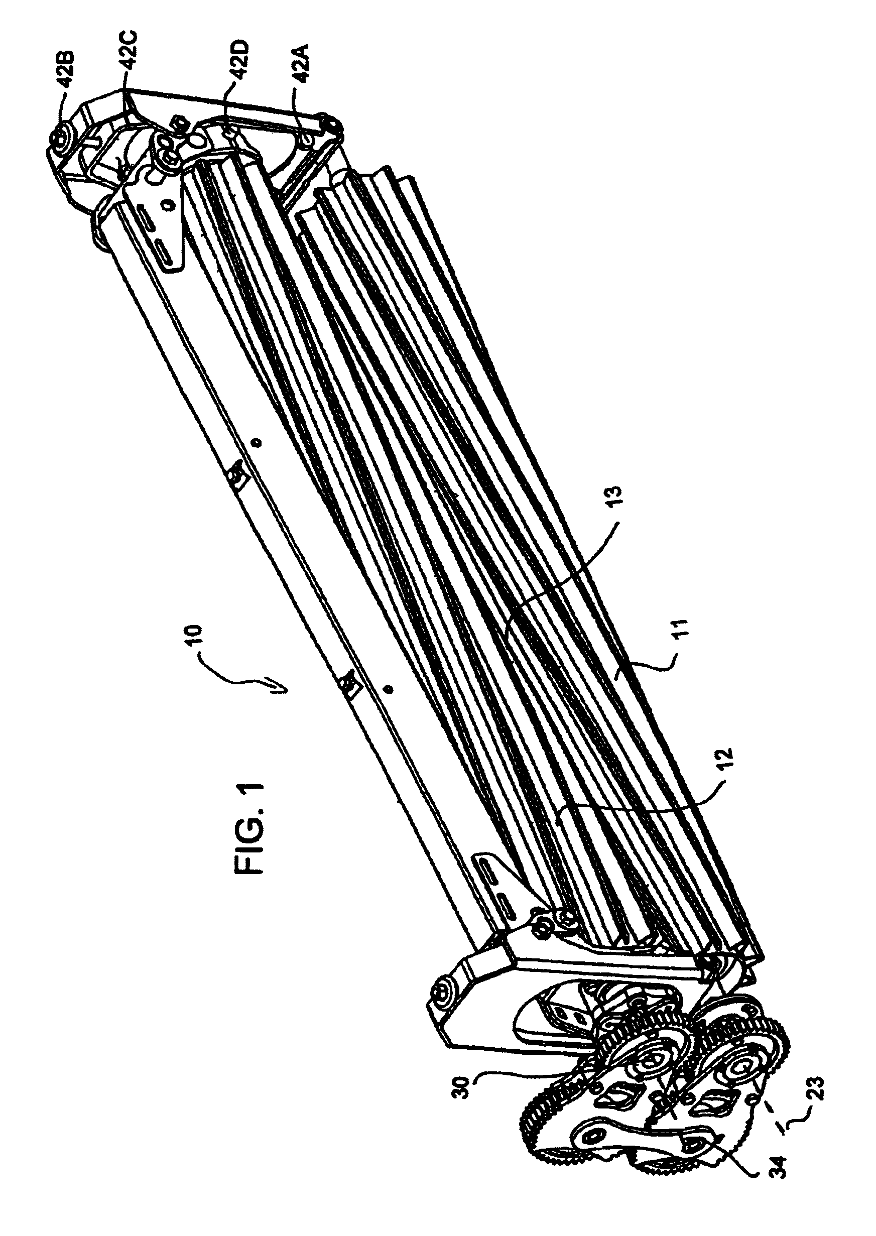
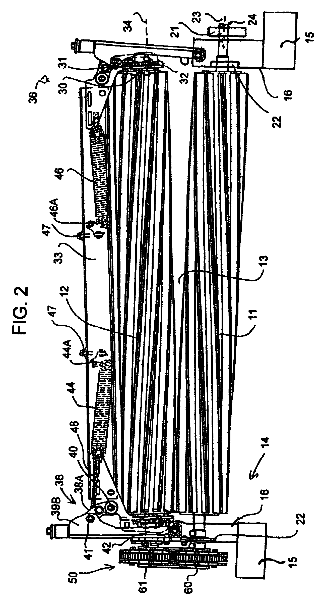
[0090]A forage conditioner 10 comprises a first bottom roll 11 and a second top roll 12 which meet in a central area 13 through which the crop material passes in a conditioning action. The crop conditioner is mounted on a crop harvesting machine 14 the only part of which is shown is the supporting leg 15 which extends from a main frame structure downwardly and forwardly to provide support for a back sheet and a table.

[0091]The construction and arrangement of conditioners of this general type on a crop harvesting machine, particularly a swather is well known to one skilled in the art so it is not necessary to describe in detail the cooperation between the conditioning assembly and the harvester itself.

[0092]In general, the bottom roll 11 is fixed relative to a support housing 16 which is in turn mounted on the leg 15 so that the crop passes over the bottom roller 11 while that roller remains fixed in place between the leg 15 and a corresponding leg at the opposite end of the rollers ...


PUM


Abstract

A forage conditioner for conditioning cut crop material from a forage harvester includes a fixed bottom fluted roller carried in end housings and a top fluted roller which is pivotally mounted on the housings by a linkage pivotal relative to the housing about an axis lying in a plane at right angles to the roller axes so that the top roller is liftable from crushing position against the bias of a spring extending along the top roller. Rotation of the bottom roller is transferred to the top roller through a gear train which includes two idler gears each mounted on a respective arm with the arms constrained to move symmetrically relative to the rollers by intermeshing teeth on the arms so as to control the angular timing of the rollers to ensure accurate intermeshing of the flutes.

Description

[0001]This application claims priority under 35 U.S.C. 119 from U.S. Provisional Application Ser. No. 60 / 635,954 filed Dec. 15, 2004.[0002]This invention relates to a conditioning roller assembly of the type for use in a hay or other forage crop conditioner.BACKGROUND OF THE INVENTION[0003]Hay conditioners generally include a pair of rollers mounted in co-extensive parallel relationship for rotation about respective axes with the crop arranged to pass between the rollers in a conditioning action.[0004]Each of the rollers carries a plurality of longitudinally extending angularly spaced flutes which project outwardly from the surface of the roller. The rollers are spaced by a distance such that the flutes intermesh generally without contact between the rollers. The intermeshing of the flutes causes the crop material to be bent as it passes between the rollers causing a cracking of the waxy surface of the crop stem.[0005]It is necessary in such rollers to allow one of the rollers, gene...

Claims


Application Information

Patent Timeline
Patent Type & Authority Patents(United States)
IPC IPC(8): A01D61/00
CPCA01D82/02
Inventor FOX, THOMAS RUSSELLENNS, JOHN EDWARDSNIDER, GEOFFREY U.DUNN, JAMES THOMAS
Owner MACDON INDS
Learn More