Hydrodynamic brakes

a technology of hydraulic brakes and brakes, which is applied in the direction of fluid couplings, rotary clutches, couplings, etc., can solve the problems of increasing energy consumption, occupying a substantial amount of construction space, and the flow cycle in the working space between the pump wheel and the turbine wheel cannot effectively transfer the revolution momentum from the pump wheel to the turbine wheel, etc., to achieve stability of function and long life.

Inactive Publication Date: 2007-03-13
VOITH PATENT GMBH
View PDF10 Cites 15 Cited by
  • Summary
  • Abstract
  • Description
  • Claims
  • Application Information

AI Technical Summary

Benefits of technology

[0013]This task is solved by creating between the rotor and the hollow shaft, a connection which is on the one hand torsionally strong and which on the other hand, however, allows for axial relocatability.
[0014]In a further development of the invention in one form thereof return springs are provided which drive the rotor away from the stator during non-braking operation. In order to prevent these return springs from being subject to tilting on the longitudinal axis during the shift revolution movement of the rotor, which could lead to an early function-impedance and the destruction of the springs, measures have been taken to make possible a free turning of the springs around the longitudinal axis of the rotor. It is in particular advantageous that measures can be taken to ensure that the springs can freely turn around their own axis during the traveling of the rotor in an axial direction. In this way the opening and closure of the working space during the transfer from braking operation to non-braking operation or, respectively, vice-versa, can take place without any hindrance. The springs, which act upon the rotor in an axial direction, constantly work as guided and tilt-free and, for this reason, have a stability of function and a long life duration. They are thereby at all times freely rotational so that they cannot be subjected to any disadvantageous torsion forces.

Problems solved by technology

This produces an undesirable braking momentum and thereby power dissipation which increases the energy consumption.
Such a design is elaborate and furthermore occupies a substantial amount of construction space.
As soon, however, as this loading is reduced, or when the drive line moves over into coast drive, that is to say when the output shaft rotates at a higher revolution speed than the drive shaft, the spring force becomes predominant and pushes the pump wheel into a position at a distance away from the turbine so that the flow cycle in the working space between pump wheel and turbine wheel can no longer effectively transfer a revolution momentum from the pump wheel to the turbine wheel.

Method used


Image

  • Hydrodynamic brakes
  • Hydrodynamic brakes
  • Hydrodynamic brakes

Examples


Embodiment Construction

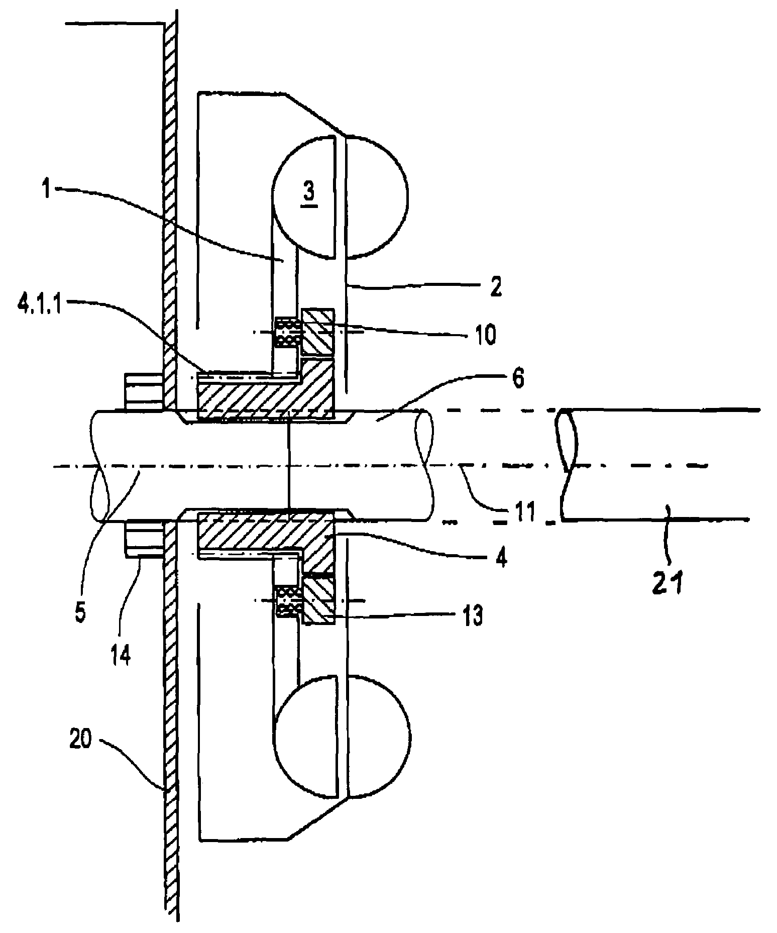
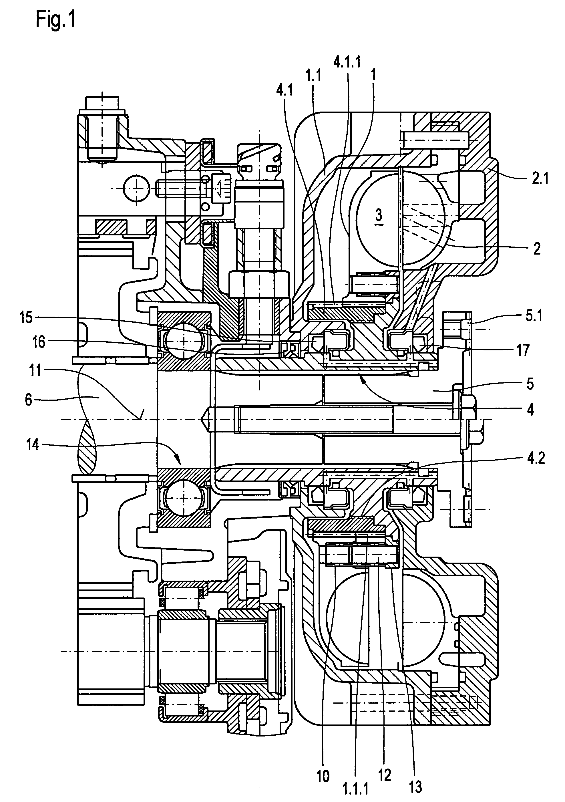
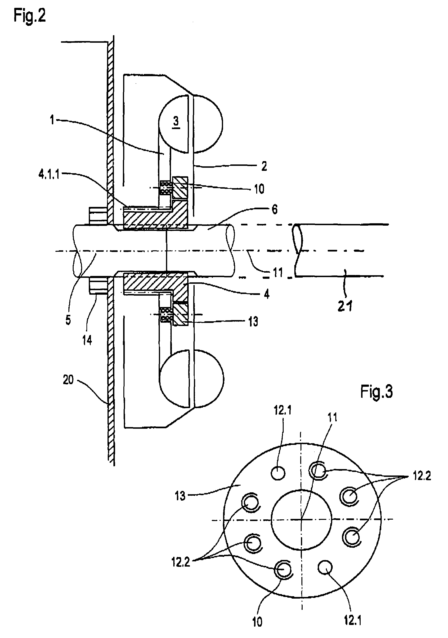
[0020]The rotor illustrated in FIG. 1 is made up as follows: a rotor 1 and a stator 2 are each of them developed as impeller wheels and form with one another a torus-shaped working space 3. The rotor sits upon a hollow shaft 4. This is torsionally firmly connected with a shaft 5 which is close to a prop shaft, which is not shown here, as well as a shaft 6 which is close to a transmission not shown here. The shaft 5 is insertable into the hollow shaft 4. It is provided with a flange 5.1 for the transfer of torsional momentum.

[0021]Stator 2 features a stator casing 2.1. rotor 1 features a rotor casing 1.1.

[0022]Rotor 1 is indirectly borne by the hollow shaft 4. The hollow shaft 4 for its part bears a ring follower 4.1. This features on its outside circumference a coarse-pitch screw thread 4.1.1. Rotor 1 is on its inside circumference provided with an appropriate coarse-pitch screw thread 1.1.1. The screw threads 4-1-1 and 1.1.1 work together with one another. They have a screw pitch t...


PUM


Abstract

A retarder having the following features: a rotor (1) and a stator (2) that, together, form a working space (3); a hollow shaft (4) for connecting, in a rotationally fixed manner, an input shaft (5), which is near a transmission, to an output shaft (6), which is near a cardan shaft, and; the hollow shaft support s the rotor by means of a screw thread (4.1.1).

Description

CROSS-REFERENCE TO RELATED APPLICATION[0001]This application is related to and claims the benefit under 35 U.S.C. §119 and 35 U.S.C. §365 of International Application No. PCT / EP2003 / 03407, filed Apr. 2, 2003.BACKGROUND OF THE INVENTION[0002]The invention refers to a hydrodynamic brake, generally known as “retarder”, in particular for motor vehicles.[0003]Such retarders contain two impeller wheels of which one stays fixed (the stator) and the other revolves (the rotor) The two impeller wheels together form a torus-shaped working space. This working space is used for the purpose of braking and is to this end filled up with a work medium, for example with oil, whereas in the non-braking operation area no work medium is present.[0004]In this working space in the non-braking area there is present, however, air. This produces an undesirable braking momentum and thereby power dissipation which increases the energy consumption.[0005]Numerous measures have become known with the intention of ...

Claims


Application Information

Patent Timeline
Patent Type & Authority Patents(United States)
IPC IPC(8): F16D57/00F16D57/04
CPCF16D57/04
Inventor VOGELSANG, KLAUSEBERLEIN, WALTERDEEG, MARTIN
Owner VOITH PATENT GMBH
Why Eureka
Try Eureka