
Adjustment apparatus

a technology of adjustment apparatus and substrate, which is applied in the direction of rotary conveyors, conveyor parts, transportation and packaging, etc., can solve the problem that the substrate cannot be easily broken, and achieve the effect of not easily broken, reduced associated cost of the adjustment apparatus, and increased yield

Active Publication Date: 2007-03-13
CHUNGHWA PICTURE TUBES LTD
View PDF9 Cites 23 Cited by
  • Summary
  • Abstract
  • Description
  • Claims
  • Application Information

AI Technical Summary

Benefits of technology

[0009]As the substrate can use point friction from the pin and roller friction from the joinball, the substrate will not fail easily, and a robot or human being can handle the substrate. Because the substrate is raised by the pin up device, the substrate will not easily be broken when the robot or human takes the substrate. Therefore, the yield is increased. In addition, the pin and the joinball are positioned in a ratio of 1:1 so that the associated cost of the adjustment apparatus is decreased.

Problems solved by technology

Because the substrate is raised by the pin up device, the substrate will not easily be broken when the robot or human takes the substrate.

Method used


Image

  • Adjustment apparatus
  • Adjustment apparatus
  • Adjustment apparatus

Examples


Embodiment Construction

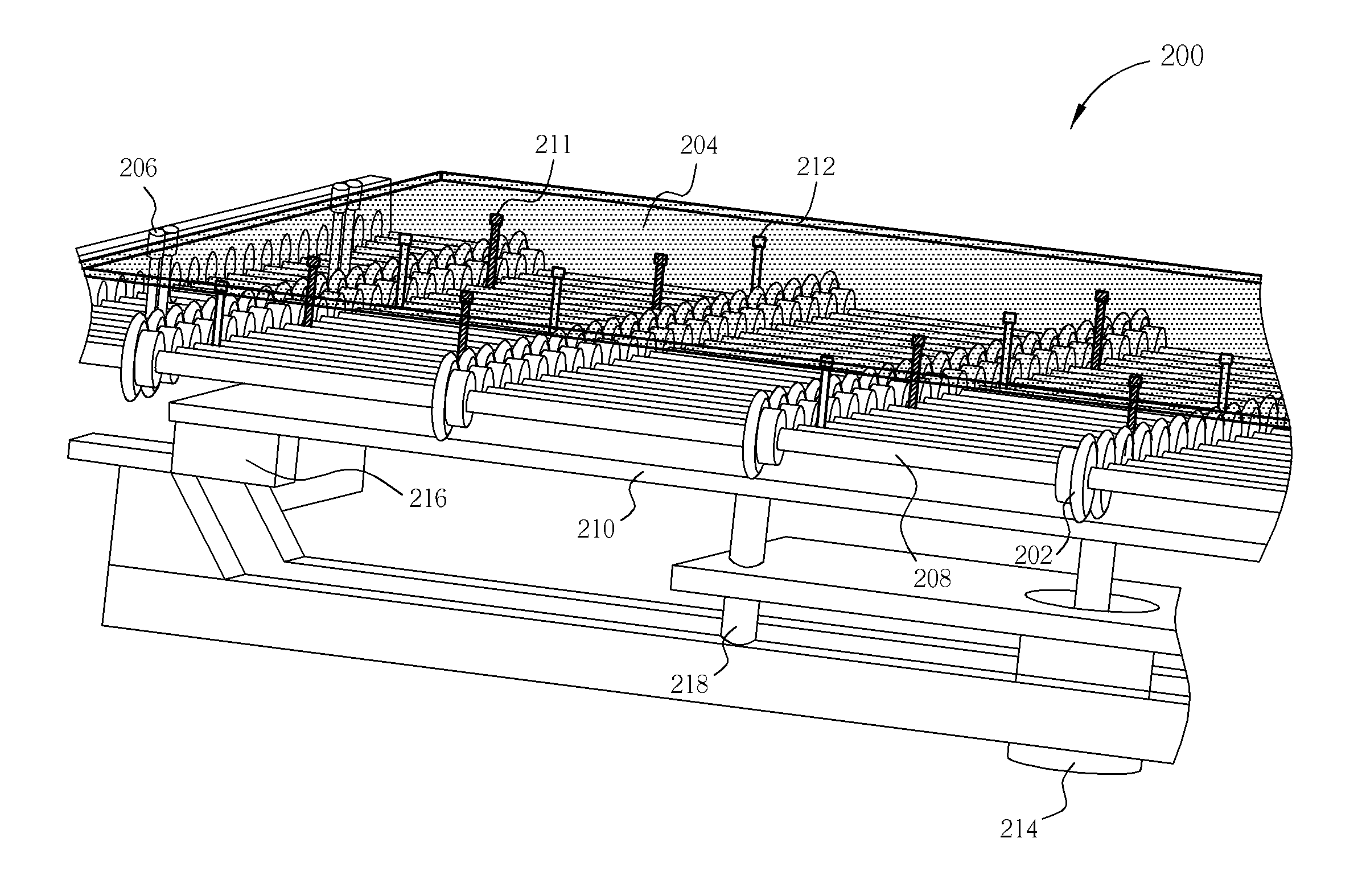
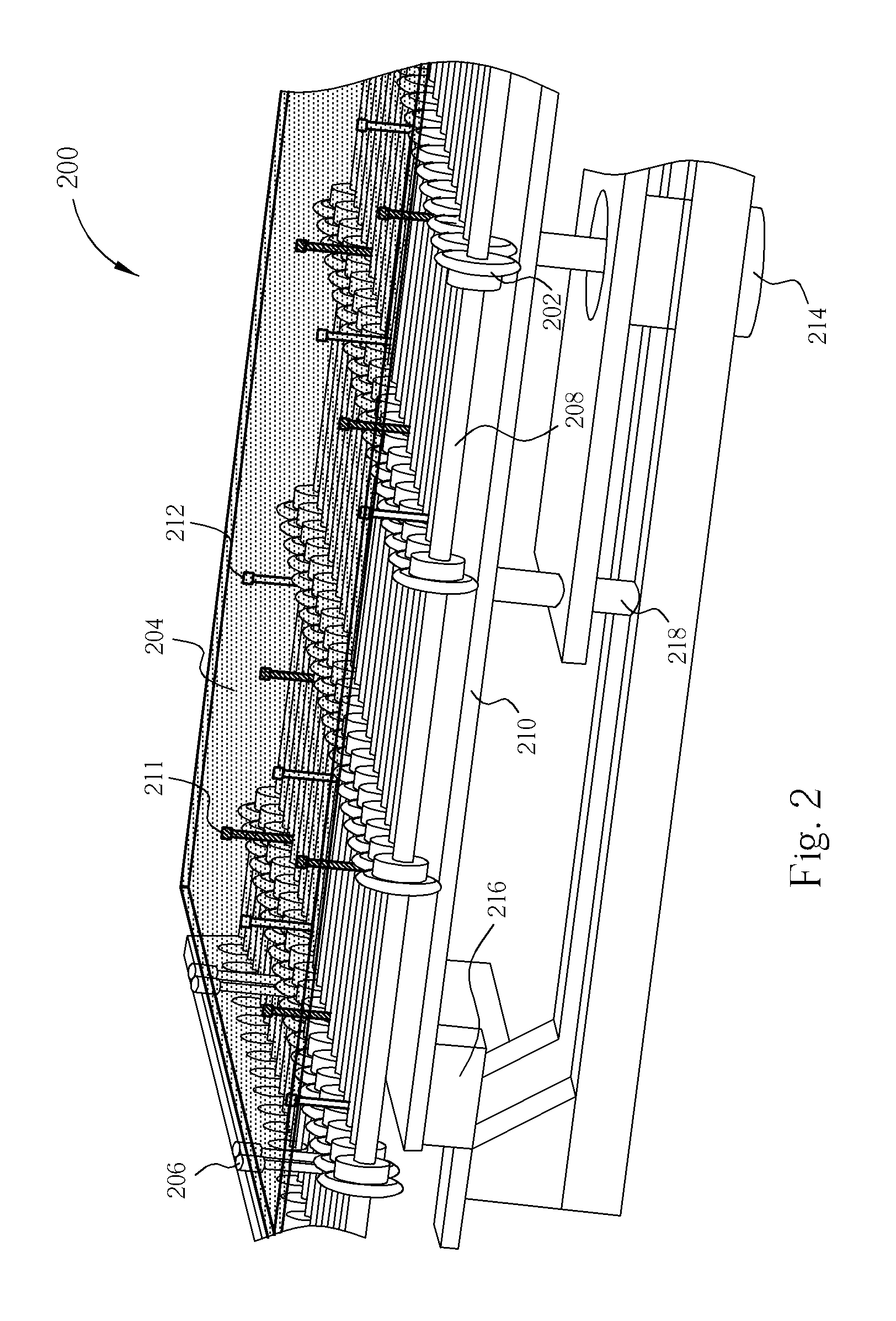
[0016]Please refer to FIG. 2. FIG. 2 is a schematic diagram of a structure of an adjustment apparatus according to an exemplary embodiment of the present invention. An adjustment apparatus 200 is a substrate adjustment apparatus of a CF glass, TFT glass, or pure glass substrate. Before the substrate 204 proceeds to a next process, the substrate 204 needs to first have its position adjusted. Then, a robot or human moves the substrate to an inspection or repair tool. As shown in FIG. 2, the adjustment apparatus 200 comprises a roller 202, a transport rail 208, a pin up device 210 and an adjustment device 206. Each transport rail 208 has a plurality of rollers 202 at a fixed distance from each other. A linear bearing 218 drives the transport rails 208 for rolling the rollers 202, so the substrate 204 is moved to an adjustment device 206. The pin up device 210 is driven by a low speed pneumatic cylinder 214, and the pin up device is raised slowly. A plurality of pins 211 and a plurality...


PUM


Abstract

An adjustment apparatus, which is able to adjust a substrate position. The apparatus includes a plurality of transport rails, a plurality of rollers on each transport rail, a pin up device and an adjustment device. The roller is transported the glass substrate, a pin and a joinball of the pin up device are supported and are raised the substrate from the roller. Finally, an adjustment device can adjust the glass substrate.

Description

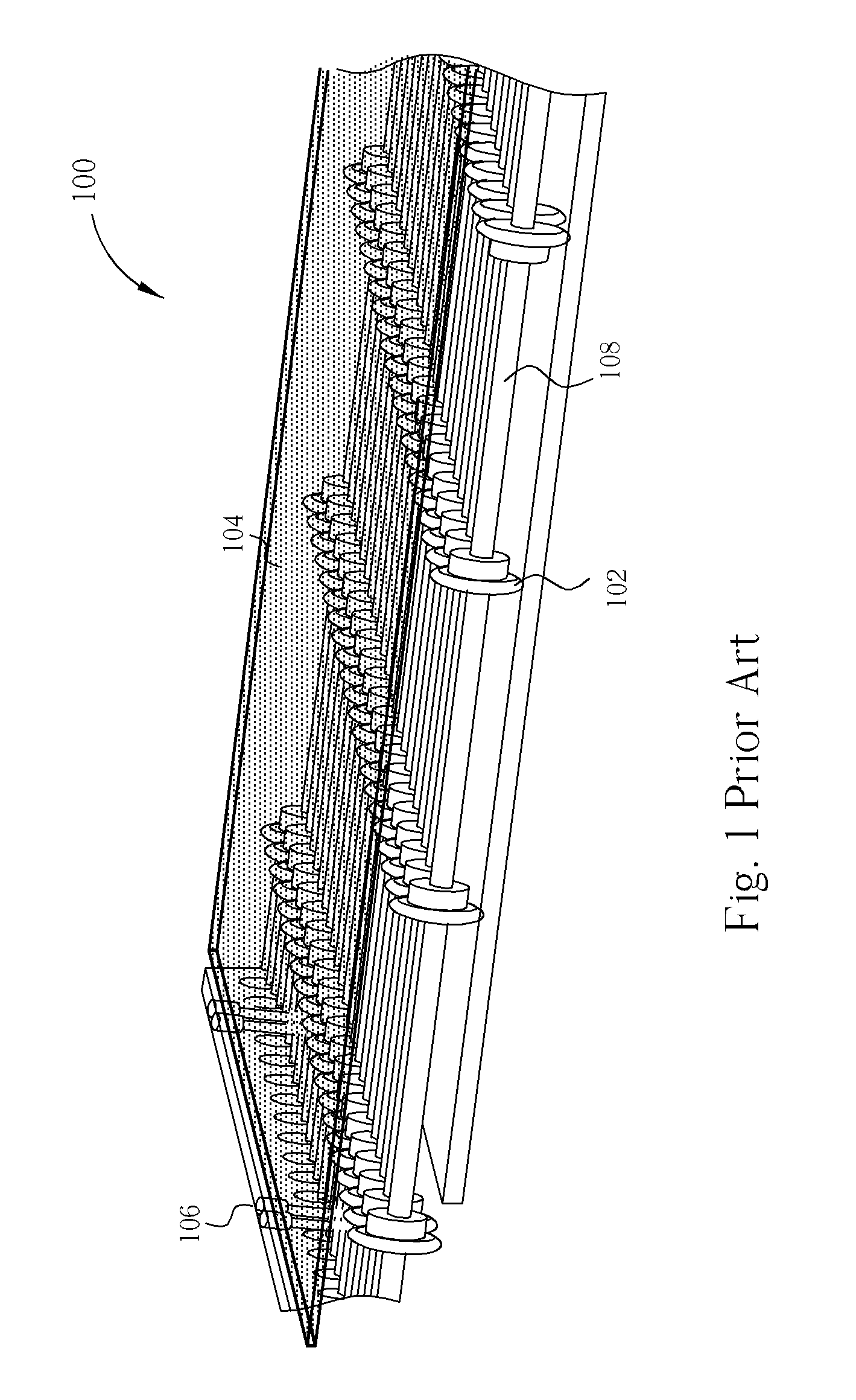
BACKGROUND OF THE INVENTION[0001]1. Field of the Invention[0002]The present invention relates to a substrate adjustment apparatus, and more particularly to a glass substrate adjustment apparatus having a pin up device comprising a plurality of joinballs.[0003]2. Description of the Prior Art[0004]A substrate is the key component of an LCD monitor. It dictates the cost of the LCD, and plays a decisive role in the yield. The size of the substrate becomes bigger and bigger as LCD manufacturing techniques improve. For a 5th generation LCD, the area of the substrate is 1300 millimeters by 1500 millimeters. The 6th generation LCD substrate has an area of 1500 millimeters by 1850 millimeters. However, the width of the substrate still remains between 0.6 millimeters to 1.1 millimeters, which causes the substrate to be easily broken when the substrate is adjusted by a conventional adjustment apparatus. Therefore, the yield decreases.[0005]Please refer to FIG. 1. FIG. 1 is a schematic diagram ...

Claims


Application Information

Patent Timeline
Patent Type & Authority Patents(United States)
IPC IPC(8): B65G47/24
CPCB65G47/244
Inventor WU, CHAO-HUANGYANG, SHAO-HUNG
Owner CHUNGHWA PICTURE TUBES LTD
Learn More