
Rapid medical evacuation system for trauma patients

a medical evacuation system and patient technology, applied in the direction of transportation items, transportation and packaging, item transportation vehicles, etc., can solve the problems of reducing the mobility of the vehicle, affecting the weight distribution, and small city streets that are impassible to standard-size ambulances

Inactive Publication Date: 2007-03-13
CALZARK
View PDF10 Cites 19 Cited by
  • Summary
  • Abstract
  • Description
  • Claims
  • Application Information

AI Technical Summary

Benefits of technology

"The present invention is a medical evacuation assembly for vehicles that allows for the safe and efficient transport of patients. The assembly includes a support assembly that can be installed in a vehicle with an open flat bed. The support assembly has lateral extension means that can move a stretcher attached to it in a lateral direction with respect to the flat bed. The assembly also includes a plurality of base rails and slide rails that can securely hold the stretcher in place during transport. The invention allows for the proper positioning of the stretcher and provides space for an attendant between the stretchers. The technical effects of the invention include improved safety and efficiency in transporting patients and the ability to securely hold the stretcher in place during transport."

Problems solved by technology

Following such an event, traffic jams and pedestrian congestion can make small city streets impassible to standard size ambulances.
Additionally, fallen debris can create off-road like conditions on top of normally smooth paved surfaces.
Such systems reduce a vehicle's mobility by increasing its effective width, and by negatively impacting weight distribution.
Emergency personnel wearing bulky protective clothing have a difficult time providing adequate medical care in the limited space offered by the stretcher mount systems currently used aboard narrow utility vehicles.
This system is limited in that it only allows for the transport of one patient on a stretcher.
This results in space aboard the vehicle that could be used for an additional patient, instead being occupied by a second attendant seat.
An additional disadvantage of the system is that it requires the use of multiple straps to restrain the patient and stretcher on the vehicle.
The time required to attach and tighten the straps may be detrimental to the survival of the injured parties.

Method used


Image

  • Rapid medical evacuation system for trauma patients
  • Rapid medical evacuation system for trauma patients
  • Rapid medical evacuation system for trauma patients

Examples


Embodiment Construction

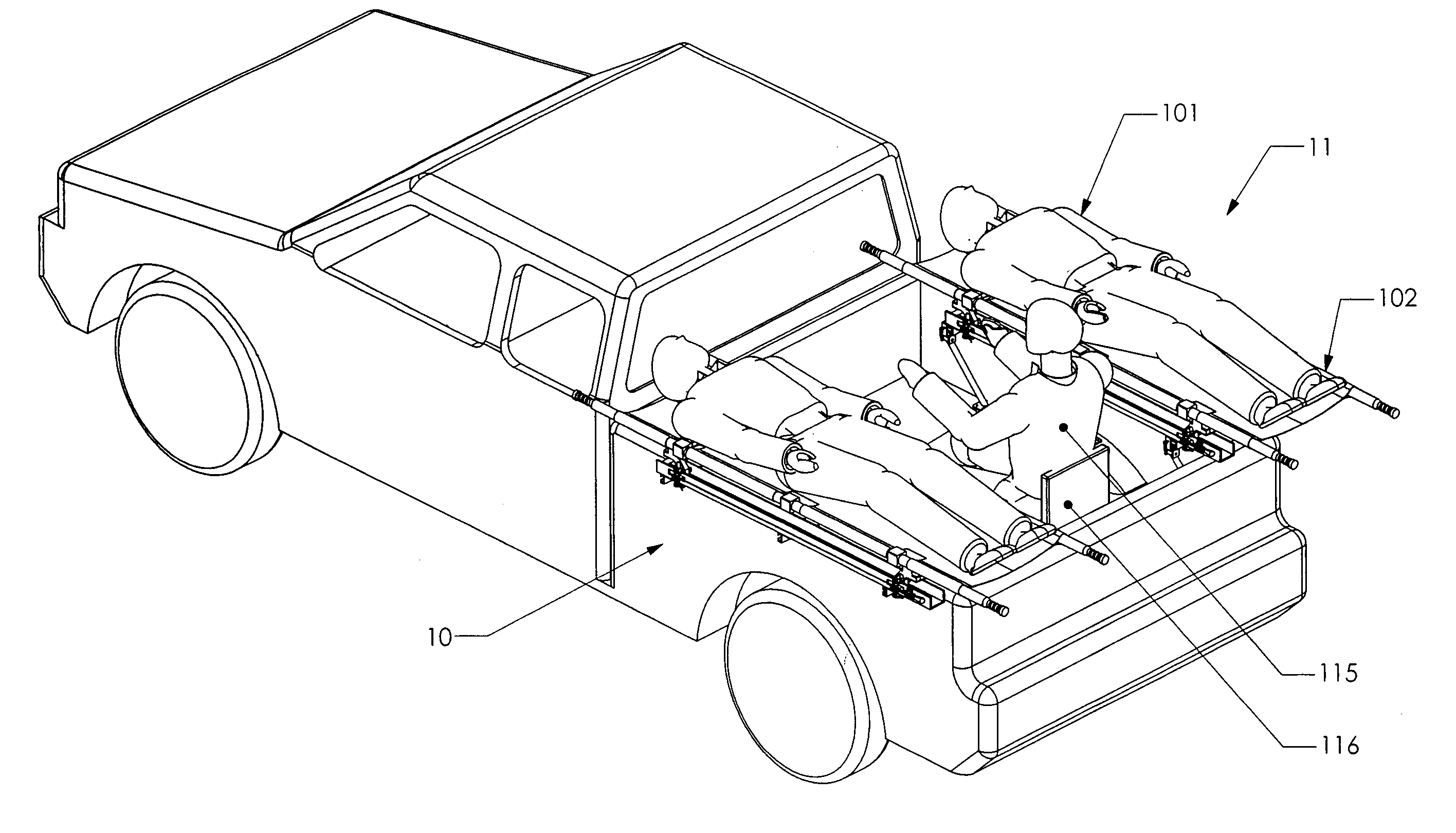
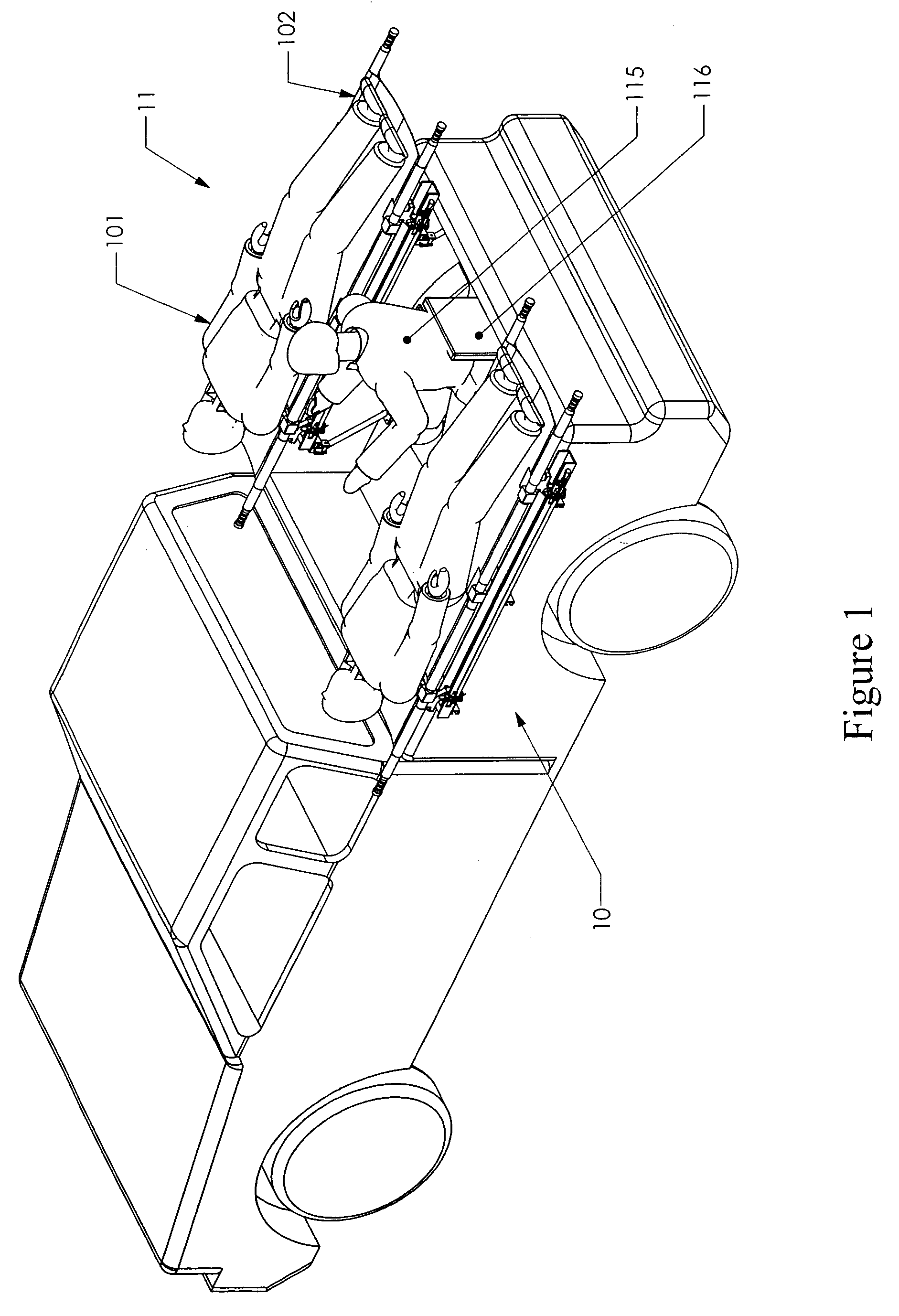
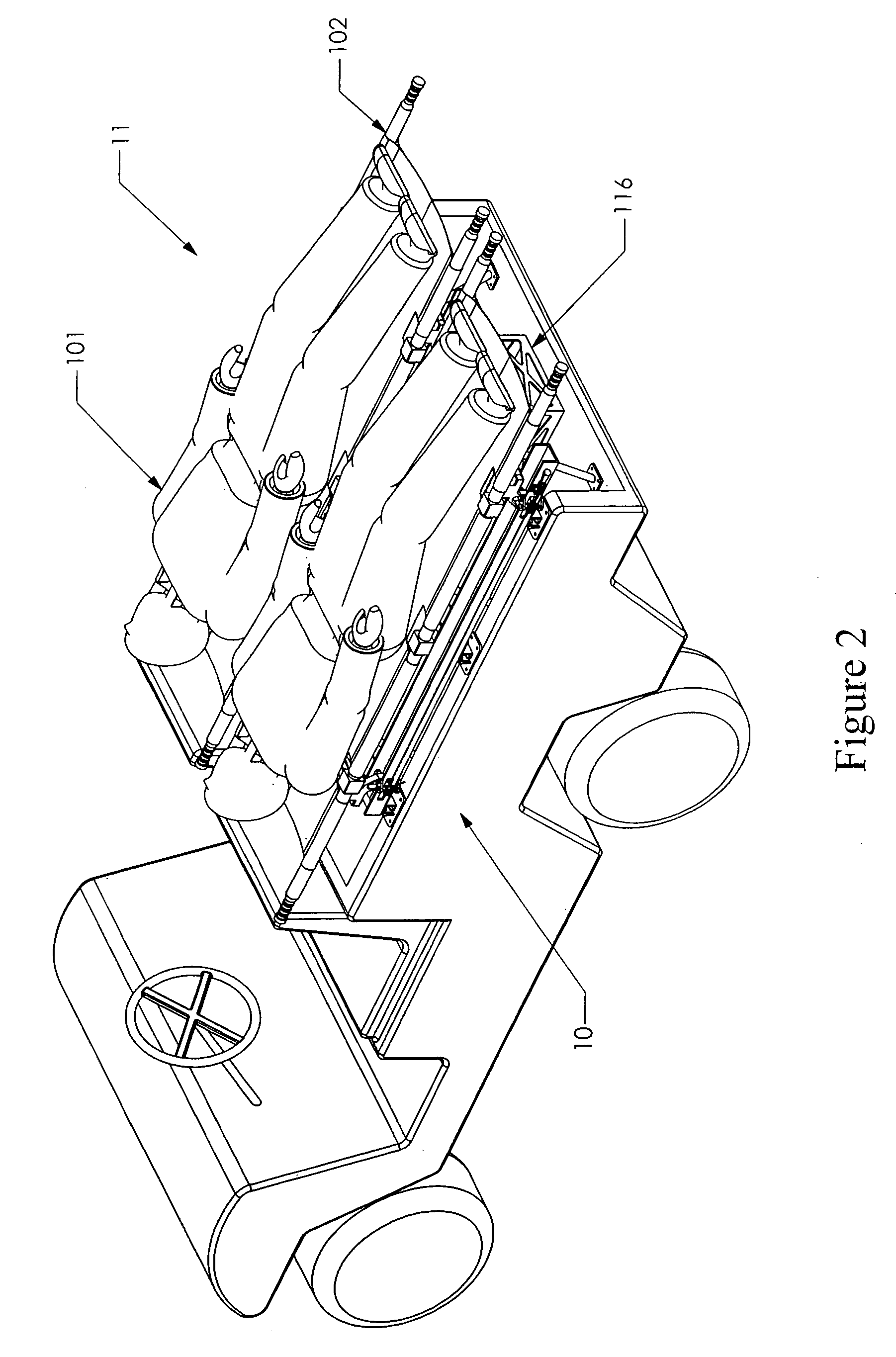
[0026]The Rapid Medical Evacuation System for Trauma Patients (RMES) in accordance with the present invention is intended to be installed in small utility vehicles that, in general, have side by side seating for a driver and passenger in front, and have a cargo bed in the rear. While the RMES is applicable to any vehicle having a rear cargo bed, its benefits are most pronounced when attached to vehicles with narrow widths. Such vehicles include small pickup trucks, off-road utility vehicles, golf karts, etc that have overall “footprint” widths between 50 and 70 inches.

[0027]With alternate reference now to FIGS. 1 and 6, the RMES system is installed in the rear cargo bed of a vehicle and comprises a left support assembly 10, a right support asssembly 11, and a collapsible attendant seat 1116. Each of the support assemblies 10 and 11 is equipped with a retention system 104, 110 (FIG. 9) that automatically engages and restrains a stretcher as it is being loaded. While the system descri...


PUM


Abstract

A system comprising an assembly of structures and supports operable for installation in a vehicle for the purpose of transporting at least one medical attendant, one patient disposed on a stretcher, and a driver on a small utility vehicle having a flat horizontal surface or “bed”. The invention provides an improved method for evacuating injured people such as, for example, injured victims of a terrorist attack, or injured soldiers from a battlefield, on a relatively narrow vehicle. The supports are arranged so that at least one patient on a stretcher or spineboard can be placed longitudinally in the bed of the vehicle with a medical practitioner positioned adjacent the patient to attend to the patient's medical needs during transport.

Description

BACKGROUND OF THE INVENTION[0001]1. Field of the Invention[0002]The present invention relates to a system for attachment to a vehicle for the transport of injured people.[0003]2. Prior Art[0004]Mass casualty events, such as wartime battles, natural disasters, and terrorist attacks, often require immediate medical care for large numbers of victims. Emergency treatment of the victims is usually initiated either near the site where the injuries occur or while the victim is in transit to a permanent medical facility. The quality of care, as well as the number of patients that can be cared for, depends greatly on the capability of the vehicles and personnel tasked with responding to the emergency. Ideally, such vehicles would be capable of carrying multiple patients, provide sufficient room for an attendant to initiate medical care while the patient(s) are in transit, and be adaptable to suit a variety of emergency situations.[0005]One such emergency situation is that of a terrorist atta...

Claims


Application Information

Patent Timeline
Patent Type & Authority Patents(United States)
IPC IPC(8): A61G1/02
CPCA61G1/06A61G3/0858A61G3/0833
Inventor FRIEDER, RUSSELLKUMARESAN, SRIRANGAMSANCES, JR., ANTHONYMYERS, WILL. J.HARVEY, L. WILLIAM
Owner CALZARK
Learn More