Turbine shroud segment attachment

a technology for turbines and shrouds, which is applied in the direction of machines/engines, liquid fuel engines, lighting and heating apparatus, etc., can solve the problems of high risk of malfunction, mechanical damage, and large complexity of mechanisms, and achieves high reliability and reliability. high, the effect of reducing the risk of malfunction

Inactive Publication Date: 2007-03-13
ROLLS ROYCE DEUT LTD & CO KG
View PDF9 Cites 24 Cited by
  • Summary
  • Abstract
  • Description
  • Claims
  • Application Information

AI Technical Summary

Benefits of technology

[0017]All these features result in an enhanced, fully automatic control of the clearance at the tips of the rotor blades. External actuating devices can be fully dispensed with.
[0018]In the case of the variant with axial clamping, the “soft” location of the individual shroud segments in accordance with the present invention is preferably accomplished by essentially T-shaped locating elements. Accordingly, the locating elements, in the cross-section, feature sideward arms with defined inclination and stiffness by which the shroud segments res

Problems solved by technology

An excessively large gap leads to flow losses, while an excessively small gap may cause mechanical damage.
This mechanism involves considerable

Method used


Image

  • Turbine shroud segment attachment
  • Turbine shroud segment attachment
  • Turbine shroud segment attachment

Examples


Embodiment Construction

[0027]The detailed description below should be read in conjunction with the summary of the invention above.

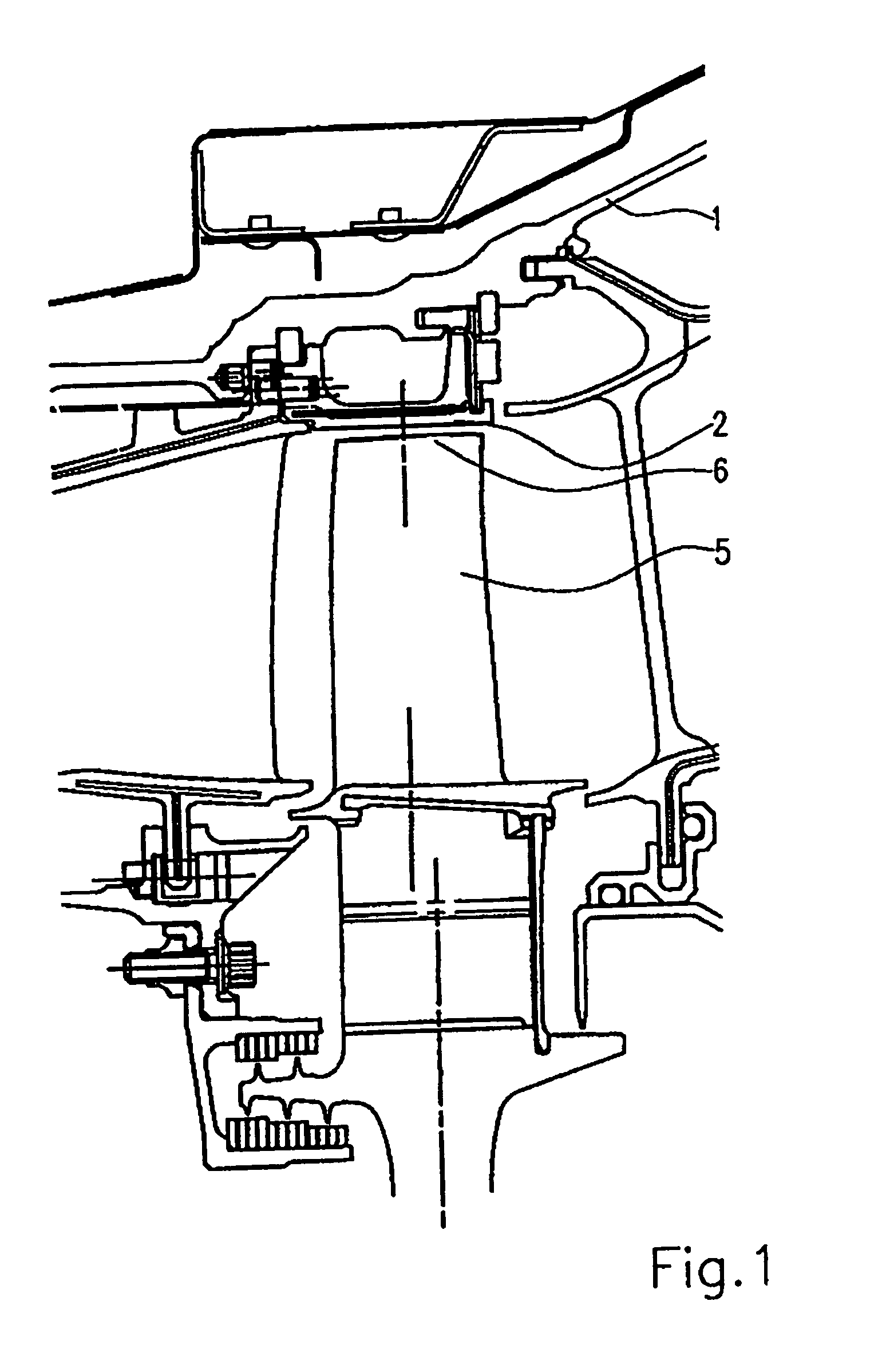
[0028]FIG. 1 shows a partial area of a turbine stage with a rotor blade 5 attached to a disk. The tip 6 of the rotor blade passes a gap along several shroud segments 2 which form a ring, as becomes apparent from FIG. 4, for example. The shroud segments 2 are located on a casing 1 in a manner still to be described.

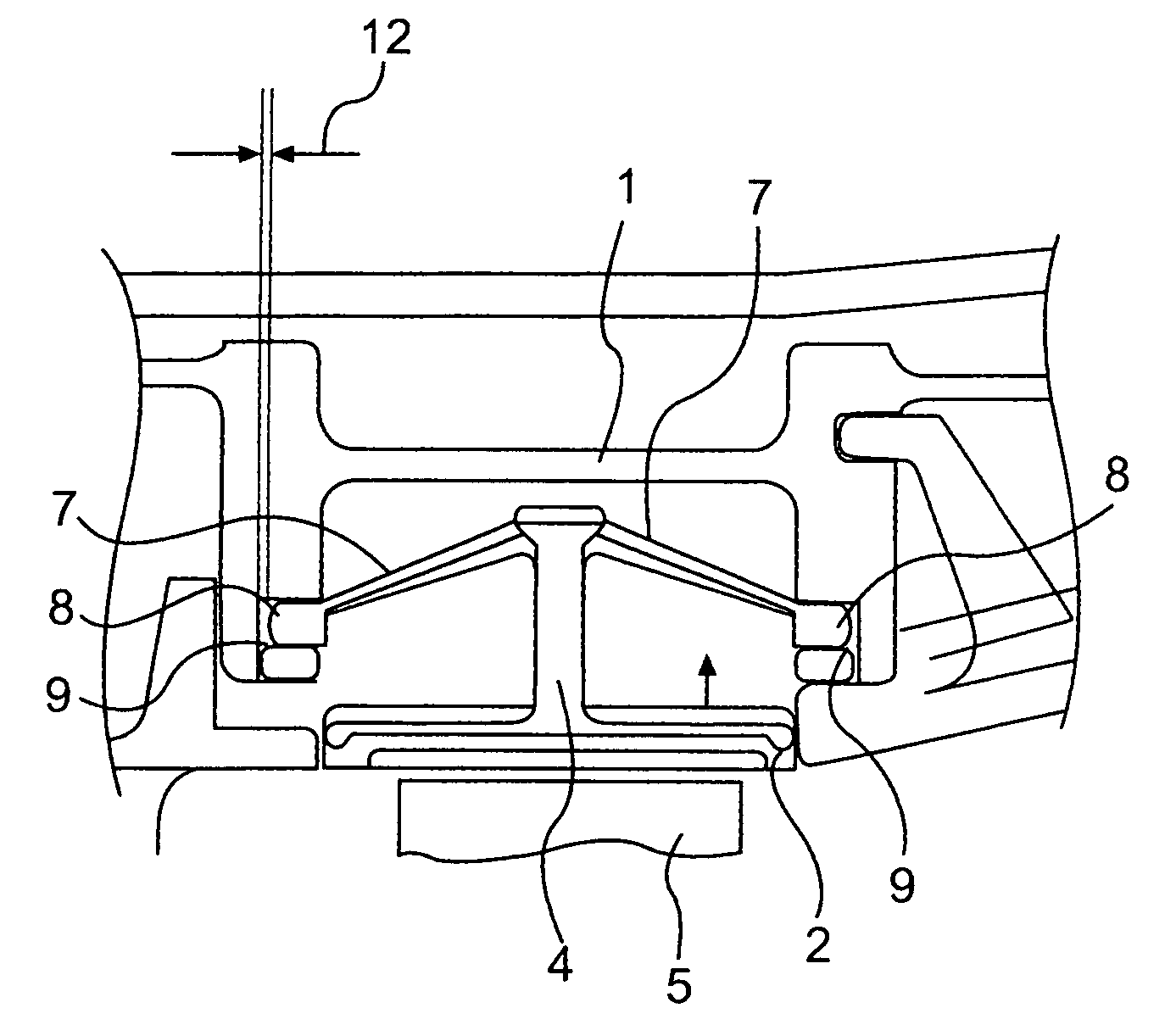
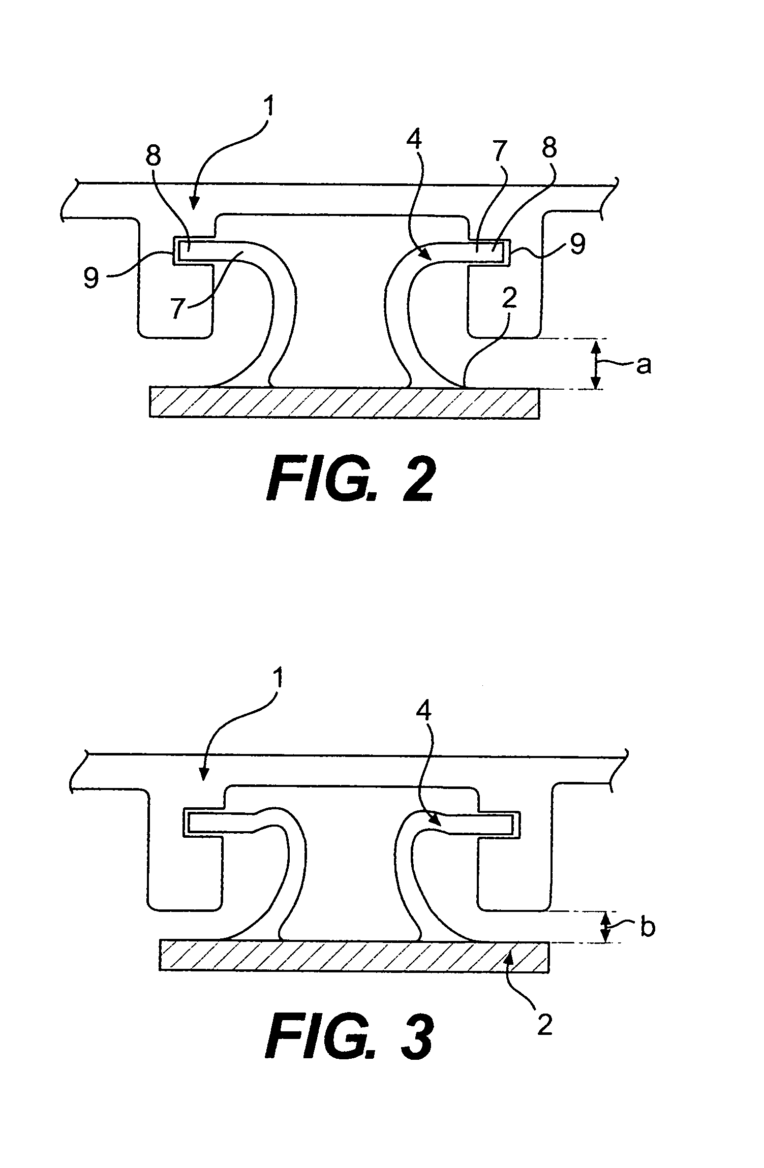
[0029]FIG. 2 shows one design of locating elements 4 for the retention of the shroud segments 2 on the casing 1. In one embodiment, the locating arms 7 are essentially elastically deformable. They are held in grooves 9 of the casing 1 by means of protrusions 8. This arrangement provides for radially outward movement of the shroud segments 2.

[0030]FIG. 4 and 5 present two views of a section normal to the center axis 10 of the gas turbine. Here, the individual shroud segments 2 and their elastic locating elements 4, in particular, become clearly apparent. FIG. 4 shows a ...


PUM


Abstract

A turbine shroud segment attachment with a casing (1) and several shroud segments (2) arranged in the casing (1), wherein the individual shroud segments (2) are located in the casing (1) with a circumferential clearance (3) between the individual shroud segments (2), in that the clearance (3) is reduced to zero at a given temperature difference between the casing (1) and the shroud segments (2), and in that the shroud segments (2) are retained on the casing (1) by way of an elastically deformable locating arrangement.

Description

[0001]This application claims priority to German Patent Application DE 10247355.2 filed Oct. 10, 2002, the entirety of which is incorporated by reference herein.BACKGROUND OF THE INVENTION[0002]This invention relates to a turbine shroud segment attachment with a casing and several shroud segments arranged in the casing.[0003]The use of shroud segments for sealing the gap at the tip of a rotor blade is known from the prior art. It is also known that the gap between the tip of the rotor blade and the shroud varies with the thermal expansion or contraction of both the rotor blade and the casing. An excessively large gap leads to flow losses, while an excessively small gap may cause mechanical damage.[0004]Normally, the individual shroud segments are located loosely on the casing with appropriate clearance, with the clearance in the axial and circumferential direction being dimensioned such that it is irrelevant for the control of the running gap if the shroud segments expand under the ...

Claims


Application Information

Patent Timeline
IPC IPC(8): F01D25/26F01D11/16F01D25/24
CPCF01D11/16F01D25/246F01D25/24
Inventor LEE, STUARTSCHIEBOLD, HARALD
Owner ROLLS ROYCE DEUT LTD & CO KG
Why Eureka
Try Eureka