Vertically-stacked plate interdigital capacitor structure

a technology of interdigital capacitors and vertical stacks, which is applied in the direction of capacitors, semiconductor devices, electrical equipment, etc., can solve the problems of reducing the overall size of electronic devices and the structure of the impedance capacitor

Active Publication Date: 2007-03-13
UNITED MICROELECTRONICS CORP
View PDF1 Cites 9 Cited by
  • Summary
  • Abstract
  • Description
  • Claims
  • Application Information

AI Technical Summary

Problems solved by technology

However, due to the requirements of electronic device miniaturization, the size of the MIM capacitor structure 10 becomes a problem in diminishing the overall size of the electronic devices.

Method used


Image

  • Vertically-stacked plate interdigital capacitor structure
  • Vertically-stacked plate interdigital capacitor structure
  • Vertically-stacked plate interdigital capacitor structure

Examples


Embodiment Construction

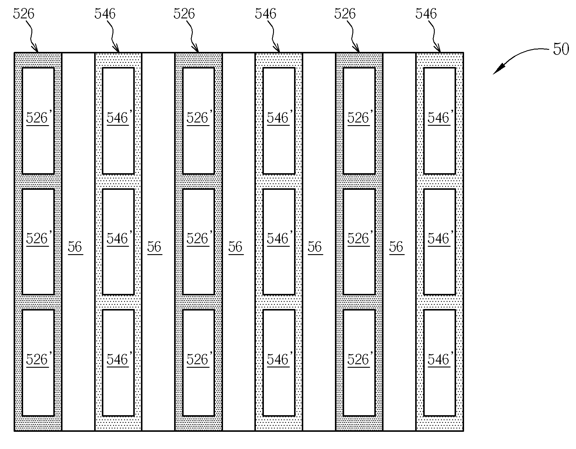
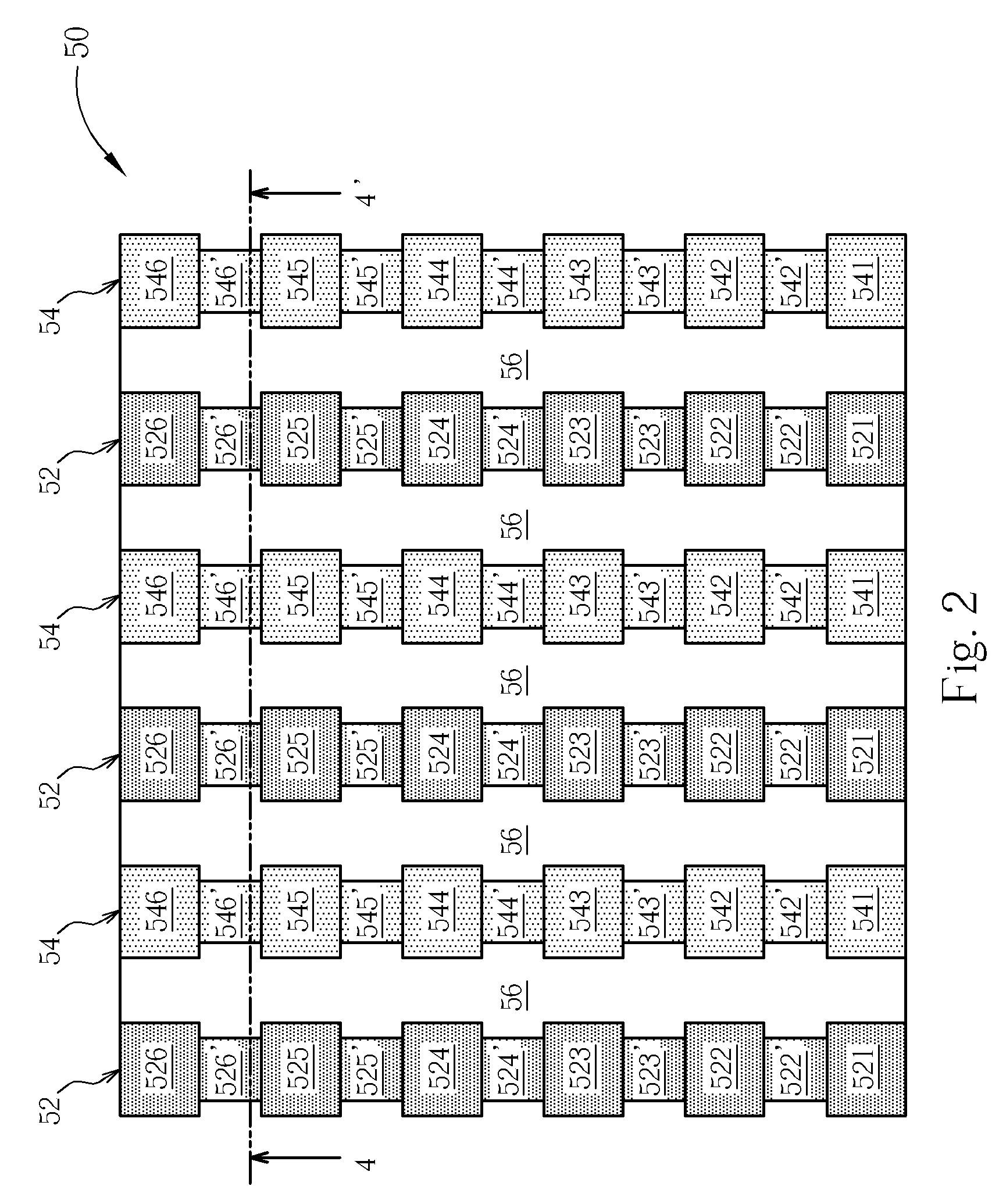
[0015]Please refer to FIG. 2 through FIG. 4. FIG. 2 is a front view of a vertically-stacked interdigital plate capacitor structure 50 in accordance with a preferred embodiment of the present invention, FIG. 3 is a side view of the vertically-stacked interdigital plate capacitor structure 50 shown in FIG. 2 where only a portion of the vertically-stacked interdigital plate capacitor structure 50 is shown, and FIG. 4 is a cross-sectional view of the vertically-stacked interdigital plate capacitor structure 50 along the tangent line 44′ in FIG. 2. As shown in FIG. 2 through FIG. 4, the vertically-stacked interdigital plate capacitor structure 50 includes at least a first conductive plate (mostly a metal plate) 52, at least a second conductive plate (mostly a metal plate) 54 parallel to the first conductive plate 52, and an inter-metal dielectric (IMD) layer 56 disposed between the first conductive plate 52 and the second conductive plate 54. The first conductive plate 52 and the second ...


PUM


Abstract

A vertically-stacked interdigital plate capacitor structure includes at least a first conductive plate, at least a second conductive plate parallel to the first conductive plate, and an inter-metal dielectric layer disposed between the first conductive plate and the second conductive plate. The first conductive plate includes a plurality of first conductive bars vertically stacked, each first conductive bar is electrically connected to the first conductive bar positioned thereunder by a plurality of first conductive vias, and each first conductive via has a rectangular shape. The second conductive plate includes a plurality of second conductive bars vertically stacked, each second conductive bar is electrically connected to the second conductive bar positioned thereunder by a plurality of second conductive vias, each second conductive via has a rectangular shape, and each second conductive via is corresponding to and parallel to each first conductive via.

Description

BACKGROUND OF INVENTION[0001]1. Field of the Invention[0002]The present invention relates to a vertically-stacked plate interdigital capacitor structure, and more particularly, to a vertically-stacked plate interdigital capacitor structure having a plurality of rectangular metal vias.[0003]2. Description of the Prior Art[0004]Various capacitor structures are used as electronic elements in integrated circuits such as radio frequency integrated circuits (RFIC), and monolithic microwave integrated circuits (MMIC). Such capacitor structures include, for example, metal-oxide-semiconductor (MOS) capacitors, p-n junction capacitors and metal-insulator-metal (MIM) capacitors. For some applications, MIM capacitors can provide certain advantages over MOS and p-n junction capacitors because the frequency characteristics of MOS and p-n junction capacitors may be restricted as a result of depletion layers that form in the semiconductor electrodes. An MIM capacitor can exhibit improved frequency ...

Claims


Application Information

Patent Timeline
Patent Type & Authority Patents(United States)
IPC IPC(8): H01L29/94
CPCH01L28/87H01L27/0805
Inventor KAO, CHING-HUNG
Owner UNITED MICROELECTRONICS CORP
Why Eureka
Try Eureka