
EAS tag with ball clutch

a technology of electronic articles and tags, applied in the direction of burglar alarm mechanical actuation, lock applications, instruments, etc., can solve the problems of deterioration of the quality of the tag, affecting the checkout area of the retail establishment, and affecting the use of the tag, so as to reduce the mass production cost, less cumbersome for the retailer, and the effect of reducing the cost of production

Inactive Publication Date: 2007-03-13
YANG XIAO HUI +1
View PDF28 Cites 58 Cited by
  • Summary
  • Abstract
  • Description
  • Claims
  • Application Information

AI Technical Summary

Benefits of technology

[0017]A primary objective of this invention is to provide an EAS security tag which is less cumbersome for the retailer to use. This EAS tag satisfies that objective as it may be detached by either the prevalent mechanical detacher as well as the magnetic detachers on the market today.
[0019]Another objective of the present invention is to provide an EAS security tag that is economical to construct for reduced mass production costs. A related objective is to create an EAS security tag that features a minimum number of discrete parts to both minimize production cost and minimize the fail rate of the article by reducing the number of moving parts within the structure of the tag.

Problems solved by technology

In some systems, the tag is encapsulated with an ink cartridge which will open and permanently destroy the protected item and make a considerable mess in the process.
In other systems, the tag is anchored with an attachment mechanism that will cause destruction of the article if it is pulled or ripped from the article.
Although novel in many respects, the Nguyen devices require yet another expensive detachment device which complicates the checkout area in the retail establishment.
Multiple styles of detachment operation systems require too much space from the perspective of the retailer.
Although perhaps effective as a shoplifting deterrent, the Rand mechanism is quite cumbersome and labor intensive to install and utilize.
Such a system is unnecessarily complicated and is not as durable or universal as a purely passive mechanism for retaining a tack shaft within the tag housing.

Method used


Image

  • EAS tag with ball clutch
  • EAS tag with ball clutch
  • EAS tag with ball clutch

Examples


Embodiment Construction

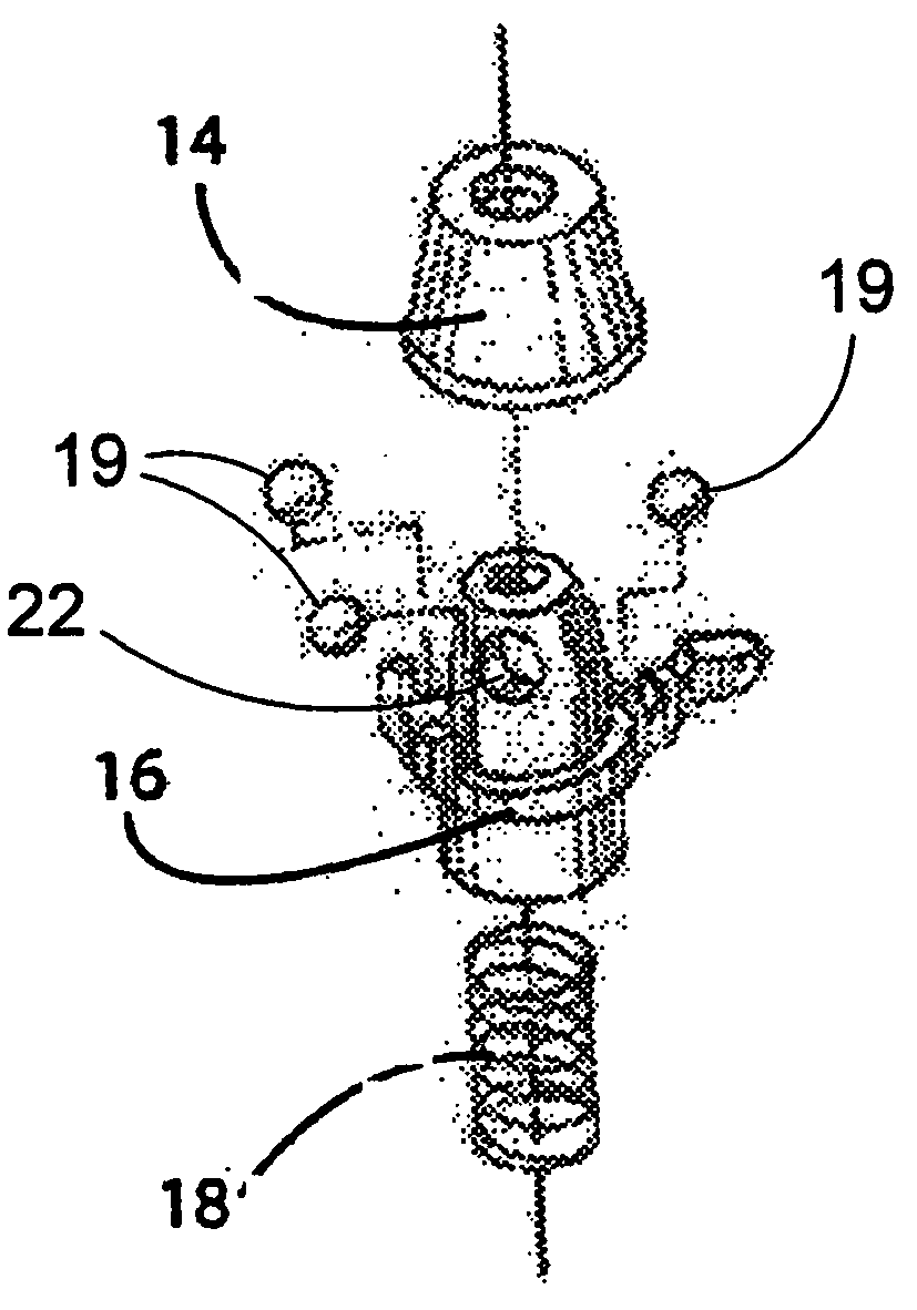
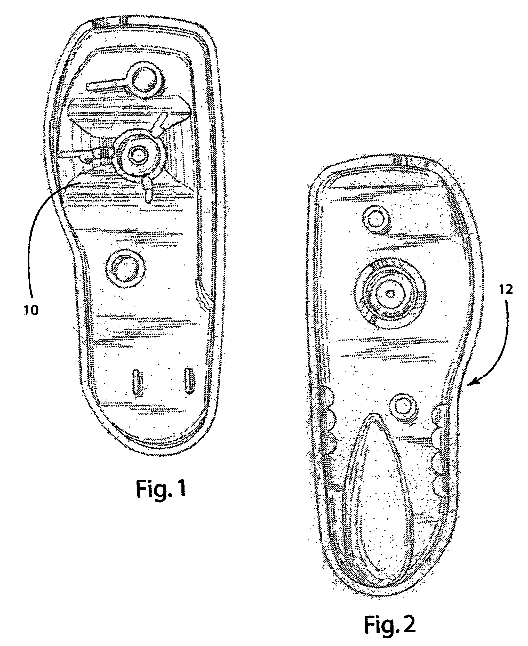
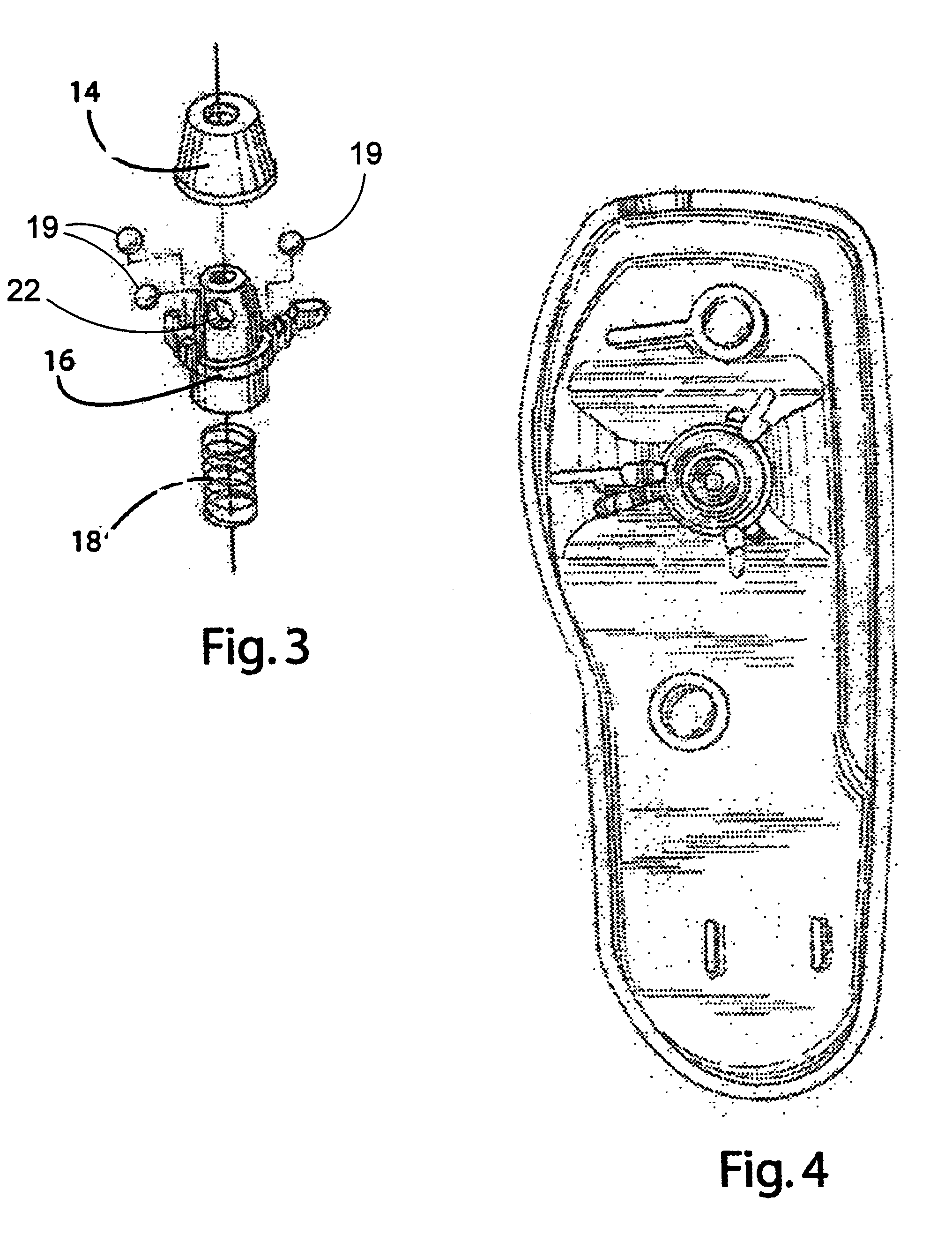
[0034]The preferred embodiment of the present invention, herein described, is a generally plastic article although other materials may also be used. The EAS tag is approximately three inches in overall length, and the tag housing consists of two molded plastic halves, a top and bottom housing structure shown as 10 in FIGS. 1 and 12 in FIG. 2, respectively. Upon assembly of top half 10 and bottom half 12, a shell is formed that houses both the fastening and release mechanisms and an electronic sensing mechanism 20 (shown in FIG. 5). Upon assembly of the tag to include the essential fastening and sensing elements, the tag is placed adjacent to the protected article and an anchoring tack 24 is inserted through both. An opening 26 in the security tag receives the anchoring tack and locks it in place such that the tack 24, and hence the security tag, cannot be removed unless a special tool is utilized to engage the release mechanism inside the security tag.

[0035]The electronic sensing el...


PUM


Abstract

An electronic article surveillance tag is claimed wherein the tag features a spindle assembly which anchors and retains a set of ball bearings which are used to clutch and retain the shaft of a tack. The spindle features an operational tab which may be contacted by the appropriate probe to turn the spindle about a central axis. The spindle is seated in a retaining means with a graduated lip around the perimeter. The turning of the spindle serves to raise a portion of the spindle from the retaining means, loosening the ball bearing grip on the shaft of the tack. The electronic article surveillance tag may be used with either a smoothed or grooved tack shaft and may be operated by either mechanical probe actuation or by the use of a magnetic detachment means applied to the spindle.

Description

CROSS REFERENCE TO RELATED APPLICATIONS[0001]This application claims priority from U.S. provisional application 60 / 468,459, filed on May 6, 2003. This application relates to an electronic article surveillance tag for use in protecting an item for shoplifting by producing an electronic signal upon entry into a pre-defined zone of interrogation. The entire disclosure contained in U.S. provisional application 60 / 468,459, including the attachments thereto, is incorporated herein by reference.STATEMENT REGARDING FEDERALLY SPONSORED RESEARCH OR DEVELOPMENT[0002]Not ApplicableBACKGROUND OF THE INVENTION[0003]1. Field of the Invention[0004]The present invention is directed to an Electronic Article Surveillance (EAS) Tag for use in shoplifting deterrence and inventory control in a retail establishment.[0005]2. Description of the Related Art[0006]EAS tags have been used for many years as a means of deterring retail shoplifting in clothing stores, electronic stores, and a myriad of other retai...

Claims


Application Information

Patent Timeline
IPC IPC(8): G08B13/14E05B73/00G08B13/24
CPCG08B13/2434E05B73/0017
Inventor YANG, XIAO HUIFUSS, ARTHUR BRADLEY
Owner YANG XIAO HUI
Learn More