Redundant water draining system of high-back-pressure units of origin station of heat supply network

A high back pressure, unit technology, applied in the directions of preheating, supplementary water supply, lighting and heating equipment, etc., can solve problems such as disturbance, unit water level influence, complex structure, etc.

Inactive Publication Date: 2014-06-25
HUADIAN POWER INTERNATIONAL CORPORATION LTD +2
View PDF8 Cites 1 Cited by
  • Summary
  • Abstract
  • Description
  • Claims
  • Application Information

AI Technical Summary

Problems solved by technology

[0006] The purpose of the present invention is to provide a redundant water drainage system for the high back pressure unit at the first station of the heating network, which solves the problem that the existing heating network condensate delivery and recovery device and its method cannot realize the rationality of the drainage flow. Distribution, complex structure, high cost, cumbersome operation, and it is easy to have the water level of the unit interacting with each other, a large disturbance abnormality, leading to the problem of overshoot, so as to meet the needs of the actual work of the heating network

Method used


Image

  • Redundant water draining system of high-back-pressure units of origin station of heat supply network
  • Redundant water draining system of high-back-pressure units of origin station of heat supply network
  • Redundant water draining system of high-back-pressure units of origin station of heat supply network

Examples


Embodiment 1

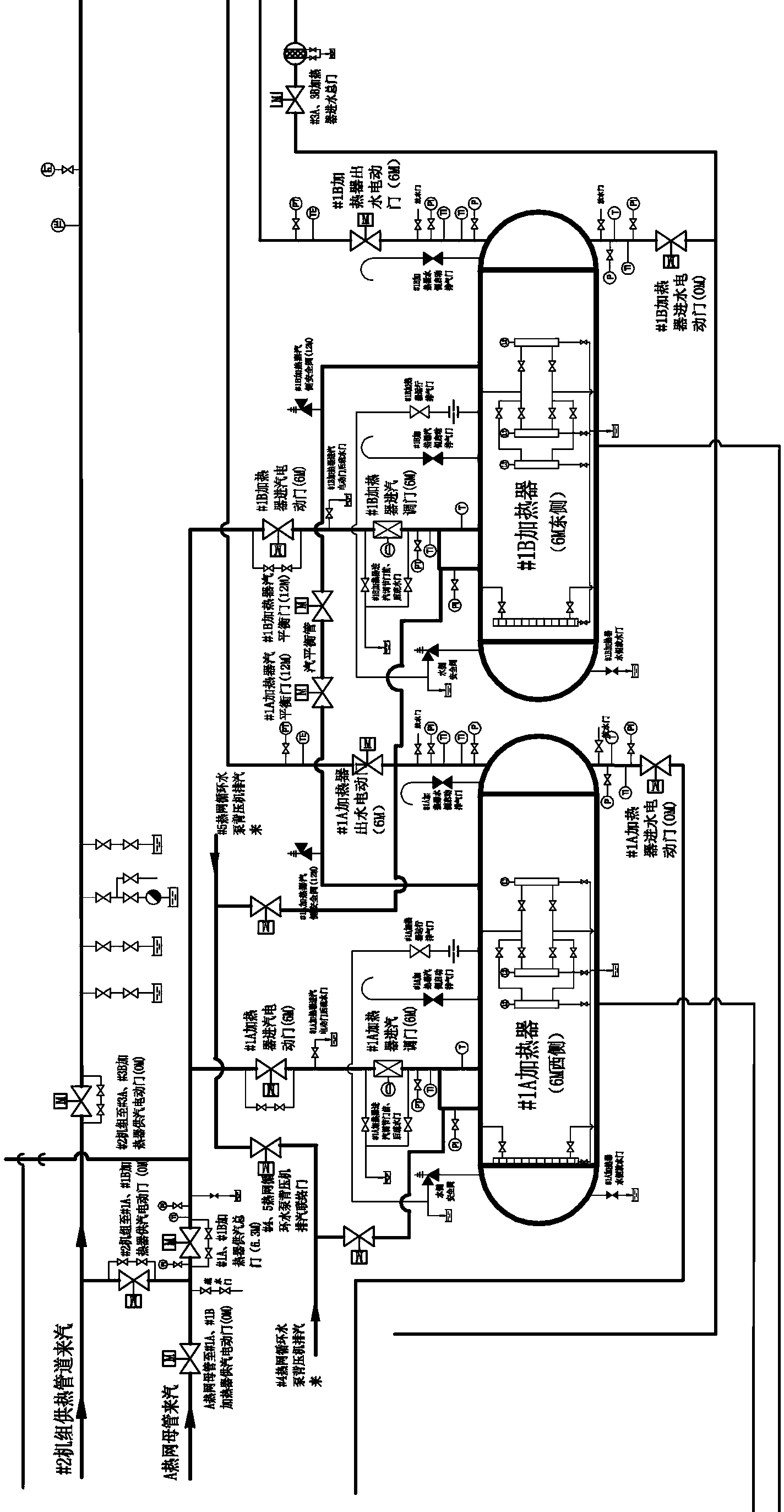
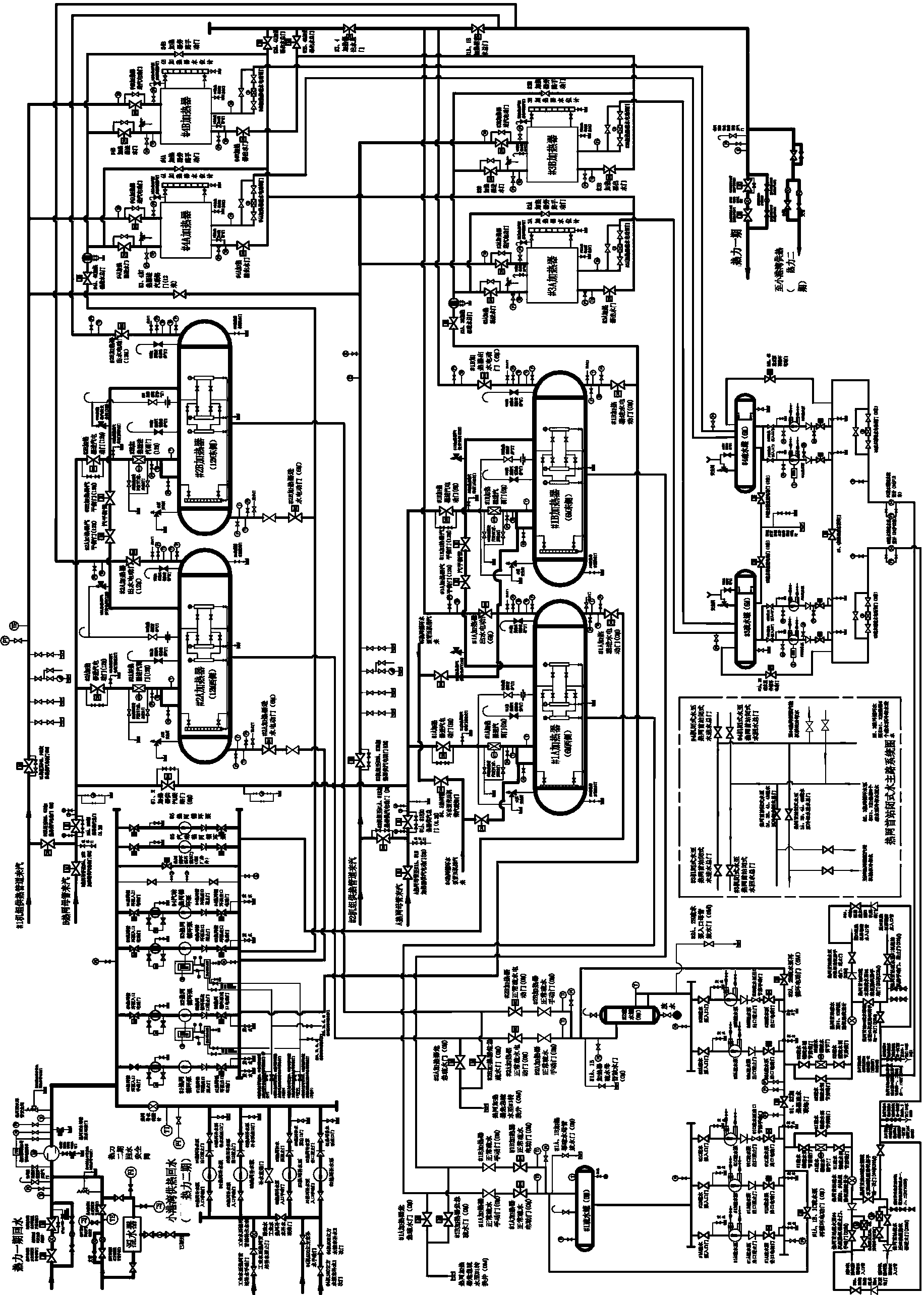
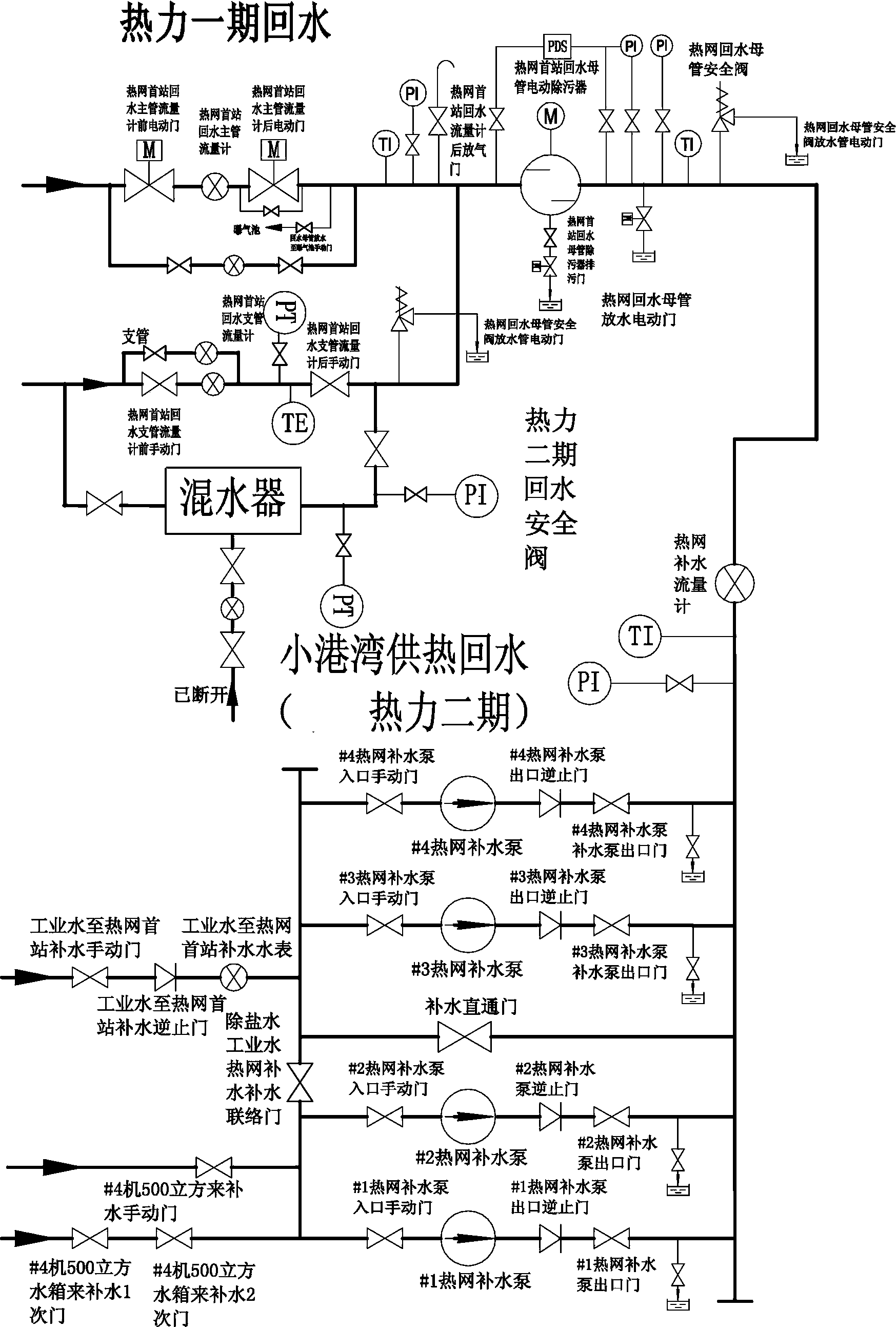
[0123] A redundant water drainage system for high back pressure units at the first station of the heating network, including unit #2 and unit #4, the sealing water of the feed pump of unit #2 and the spray water of the low pressure cylinder are all cut to the condensate water supply of the adjacent unit ; The #1A heater and #1B heater at the first station of the heating network are drained and recycled to the condensate inlet pipe of the #2 machine deaerator and the condensate inlet pipe of the #4 machine deaerator, and the return pipe is added Equipped with an electric adjustment door for drainage.

Embodiment 2

[0125] A redundant water drainage system for high back pressure units at the first station of a heating network, which is similar to Embodiment 1, except that the #2 unit is a high back pressure unit.

Embodiment 3

[0127] A redundant water drainage system for high back pressure units at the first station of the heating network, similar to Embodiment 2, the difference is that the #1A heater and #1B heater are supplied with #2 unit steam The steam is supplied from the hot pipe, and the water after heat exchange is distributed to the condensed water inlet pipe of the #4 machine deaerator through the electric control door.


PUM


Abstract

The invention relates to a redundant water draining system of high-back-pressure units of an origin station of a heat supply network. The redundant water draining system of the high-back-pressure units of the origin station of the heat supply network comprises the No.2 and No.4 high-back-pressure units of the origin station of the heat supply network. Sealing water of a feed water pump of the No.2 high-back-pressure unit of the origin station of the heat supply network and sprayed water of a low-pressure cylinder of the No.2 high-back-pressure unit of the origin station of the heat supply network are supplied to condensation water of an adjacent machine; No.1A and No.1B heaters of the origin station of the heat supply network drain water, recycle the water and feed the recycled water to deaerators of the No.2 and No.4 high-back-pressure units of the origin station of the heat supply network, and draining electric control valves are additionally arranged on return water pipelines. The redundant water draining system has the advantages that problems of incapability of reasonably distributing draining flow, complicated structure, high cost, troublesomeness in use and operation, easy influence of water levels of units, severe disturbance anomaly and excessive control of an existing condensation water delivering and recycling device of a heat supply network and a method implemented by the existing condensation water delivering and recycling device can be solved; actual work requirements of the heat supply network can be met.

Description

technical field [0001] The invention belongs to the technical field of the first station of a heating network, and relates to a redundant water drainage system for a high back pressure unit at the first station of a heating network, in particular to a redundant water drainage system for a high back pressure unit at a first station of a heating network. Background technique [0002] At present, under the high back pressure heating condition of the high back pressure unit at the first station of the heating network, the sealing water of the multi-feed water pump (30t / h) and the spray water of the low pressure tank (20t / h) are all cut to the condensate of the adjacent machine For water supply, the temperature of condensed water rises to 80°C, and some condensed water users are affected and cannot be used. If the redundant water generated by the high back pressure unit is not discharged in time, the water level of the condenser and deaerator will be high. As a result, the safe o...

Claims


Application Information

Patent Timeline
Patent Type & Authority Applications(China)
IPC IPC(8): F22D11/06F22D1/50
Inventor 张永密苏振勇李川斌王修成姜维军石德静王勇王刚王虎
Owner HUADIAN POWER INTERNATIONAL CORPORATION LTD
Why Eureka
Try Eureka