Vehicle environment monitoring device, vehicle environment monitoring method, control program and computer-readable recording medium

a vehicle environment and monitoring device technology, applied in fluid pressure control, instruments, image enhancement, etc., can solve the problems of increasing traffic accidents such as collisions or collisions of automobiles or other vehicles, high computational requirements, and high detection accuracy, so as to prevent collision accidents and improve detection accuracy. , the effect of high-quality real-time detection

Inactive Publication Date: 2007-03-13
SHARP KK
View PDF16 Cites 26 Cited by
  • Summary
  • Abstract
  • Description
  • Claims
  • Application Information

AI Technical Summary

Benefits of technology

[0037]Since the moving state of the second vehicle can be detected without using highly sophisticated calculation processing and with a small amount of calculations, a vehicle environment monitoring device can be produced at low cost without using, for example, an expensive CPU capable of high speed processing. Since real-time processing is possible with a small amount of calculations, it is not necessary to calculate and estimate the moving amount by unit time, and therefore the detection accuracy can be improved.
[0038]By performing detection processing among a plurality of frames based on image data of a specific area which is strip-shaped and longer in, and parallel to, the horizontal direction of the frame image, errors due to noise or the like can be reduced, and thus the detection accuracy can be further improved. By encompassing at least two types of colors in the specific area, the divided areas of the specific area can be prevented from having one, fixed color, and thus the sum of the areas is prevented from being the same. Thus, each sum can be relatively large. Therefore, extraction of a wrong image position time t before can be prevented. Especially, it is preferable to encompass a border between the windshield and the hood of the second vehicle in the specific area. By setting a plurality of specific areas, wrong detection or the like due to the difference in size or shape among the second vehicles as the target of detection is reduced, which can further improve the detection accuracy.
[0040]As described above, according to the present invention, the detection area can be limited to a specific area. A second vehicle which is present, for example, right rear or left rear of the moving direction can be detected without finding an extinction point, a white line or the like. Real-time processing can be performed with a small amount of calculations, which can improve the detection accuracy.
[0041]The environment of the first vehicle can be monitored so as to check by an imaging section such as a camera or the like whether there is a second vehicle which is approaching to the first vehicle in the direction of movement (e.g., right or left) of the first vehicle for, for example, turning right or turning left. When there is a danger of contact or collision, an alarm or the like can be output to notify the driver or the like of the danger. Therefore, the present invention is effective for preventing collision accidents from occurring due to failure in visual or other types of confirmation.
[0042]Thus, the invention described herein makes possible the advantages of providing a vehicle environment monitoring device capable of performing highly accurate real-time detection of a moving state of another vehicle in the environment of a vehicle having the vehicle environment monitoring device mounted thereon, a vehicle environment monitoring method using the same, a control program for causing a computer to execute the vehicle environment monitoring method, and a computer-readable recording medium having the control program recorded thereon.

Problems solved by technology

Recently, the increase of traffic accidents such as contact or collision of automobiles or other vehicles is a serious social problem.
Especially, contact or collision often occurs when the vehicle moves right or left for changing lanes, turning right, or turning left although the driver pays attention.
However, the conventional vehicle collision prevention device disclosed in the above-identified publication has the following problems.
Therefore, highly sophisticated calculations are required.
In addition to the problem regarding the quality of such highly sophisticated calculations, the calculation amount is very large because the image area E represented by the oblique lines in FIG. 11 is as large as about a half of the image plane.
Because the calculation amount is very large, real-time processing is impossible.
This makes it impossible to accurately detect the moving direction of another vehicle, and errors are likely to occur.
In addition, there are other problems that, for example, some roads do not have white lines and therefore the moving amount of the object cannot be calculated.
For these reasons, the above-described vehicle collision prevention device is not practical.

Method used


Image

  • Vehicle environment monitoring device, vehicle environment monitoring method, control program and computer-readable recording medium
  • Vehicle environment monitoring device, vehicle environment monitoring method, control program and computer-readable recording medium
  • Vehicle environment monitoring device, vehicle environment monitoring method, control program and computer-readable recording medium

Examples


Embodiment Construction

[0058]Hereinafter, a vehicle environment monitoring device and a vehicle environment monitoring method using the same according to the present invention will be described in detail by way of illustrative examples with reference to the accompanying drawings. In the following description, an automobile is used as an example of the vehicle, but the present invention is not limited to automobiles and is applicable to trucks, freight cars, two-wheel vehicles such as motorbikes and bicycles.

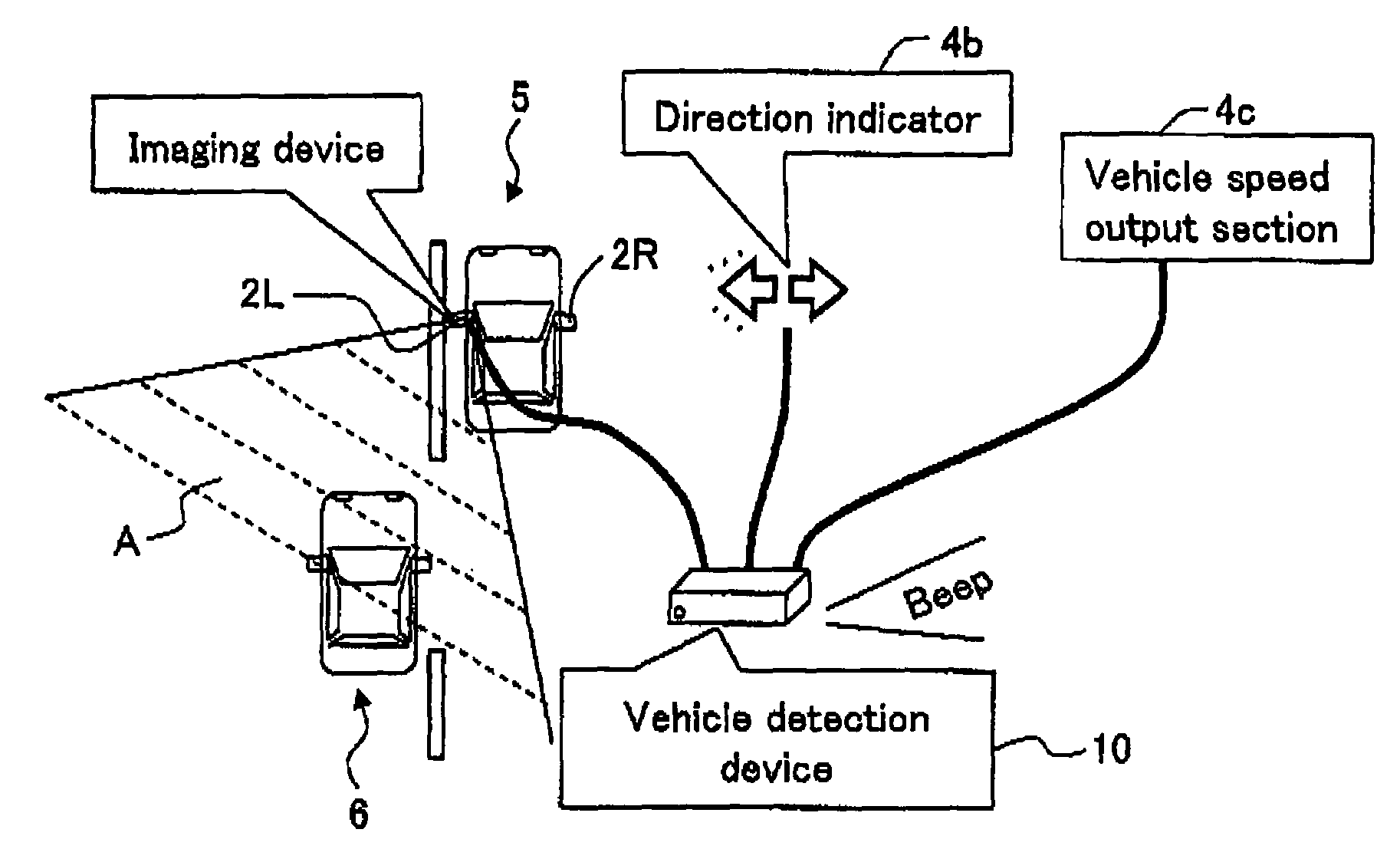
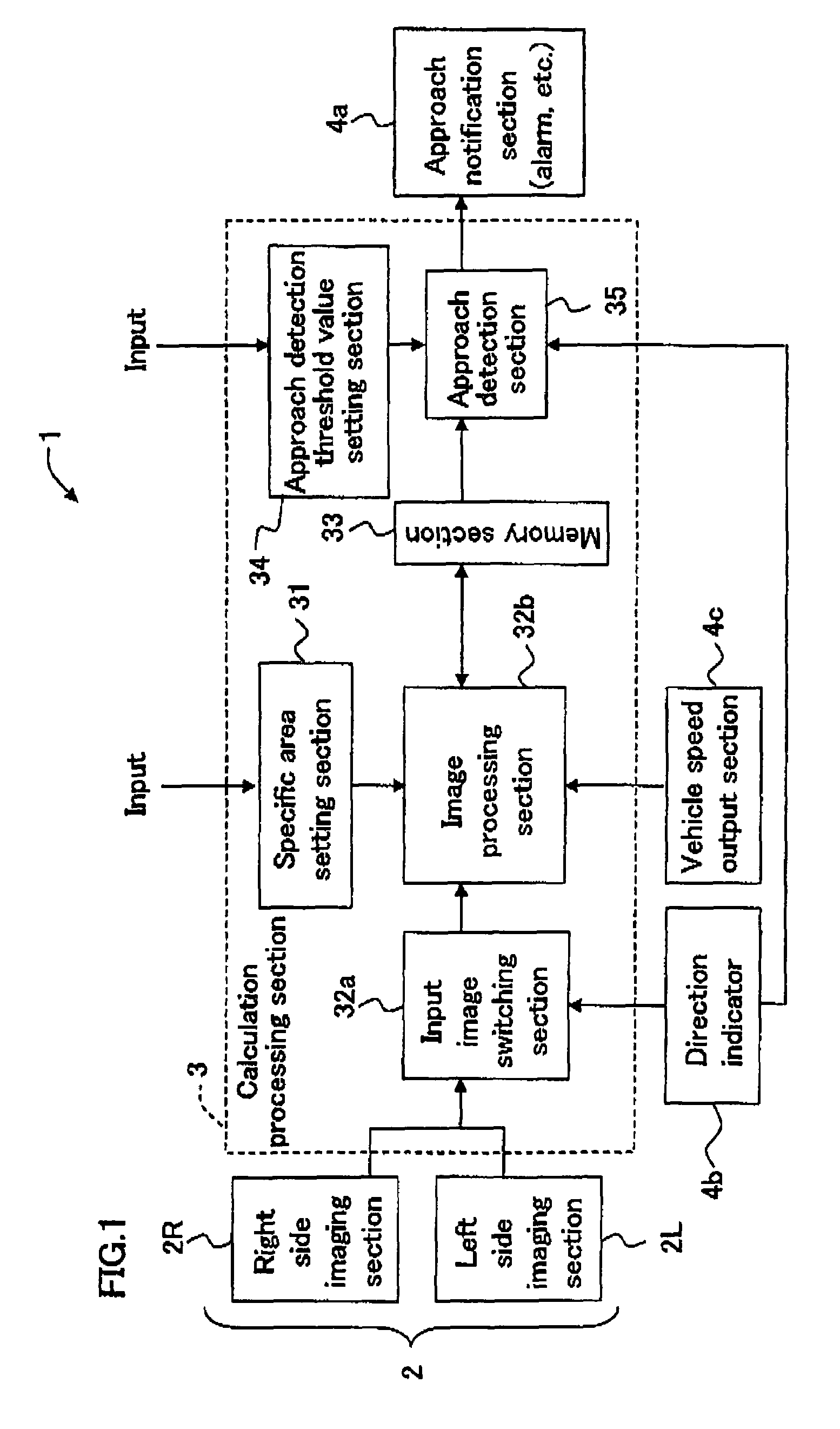
[0059]FIG. 1 is a block diagram showing an exemplary partial structure of a vehicle environment monitoring device 1 according to an example of the present invention. FIG. 2 is a plan view schematically showing the vehicle environment monitoring device 1 mounted on an automobile in one example, together with an environment thereof.

[0060]As shown in FIG. 1, the vehicle environment motoring device 1 according to this example includes an imaging section 2 for taking images of the environment of a subject o...


PUM


Abstract

A vehicle environment monitoring device comprises an imaging section for taking image data of an environment of an automobile, the image including at least two types of colors; a setting section for setting a specific area of the image data obtained by the imaging section, wherein the specific area has a strip shape longer in, and parallel to, a horizontal direction of a frame image and includes at least two types of colors; an extraction section for taking in image data of the specific area in units of one or a plurality of frame images taken by the imaging section in time series and extracting moving vector information based on the image data of the specific area; and a detection section for detecting a second vehicle which is present in an environment of a first vehicle having the vehicle environment monitoring device mounted thereon, based on the moving vector information.

Description

[0001]This non-provisional application claims priority under 35 U.S.C., §119(a), on Patent Application No. 2004-031434 filed in Japan on Feb. 6, 2004, the entire contents of which are hereby incorporated by reference.BACKGROUND OF THE INVENTION[0002]1. Field of the Invention[0003]The present invention relates to a vehicle environment monitoring device usable for performing monitoring for safety when a two-wheel vehicle such as a motorbike or a bicycle, or a four-wheel vehicle such as an automobile, which has the vehicle environment monitoring device mounted thereon moves; for example, usable for, when such a vehicle moves right or left for the purpose of turning left or turning left or for changing lanes, notifying the driver of the vehicle by means of an alarm that there is a danger of the vehicle contacting or colliding against another vehicle present in the environment thereof and thus supporting safety confirmation; a vehicle environment monitoring method using the same; a contr...

Claims


Application Information

Patent Timeline
Patent Type & Authority Patents(United States)
IPC IPC(8): G08G1/16B60R21/00B60R1/00G06T1/00G06T7/20H04N7/18
CPCB60R1/00G06T7/2013G08G1/16G06T2207/10024G06T2207/30252G06T2207/10016G08G1/166G06T7/223
Inventor NAGASAWA, SHUNSUKESATO, HIDENORIUNNO, NORIYUKI
Owner SHARP KK
Why Eureka
Try Eureka