
Radio signal transmitter with multiple antennas for improved position detection

a radio signal transmitter and multiple antenna technology, applied in direction finders, direction finders using radio waves, instruments, etc., can solve the problems of reducing system accuracy, affecting the clean reception of the rf transmission of tracked objects, and causing system errors

Active Publication Date: 2007-03-13
POSITION IMAGING
View PDF5 Cites 55 Cited by
  • Summary
  • Abstract
  • Description
  • Claims
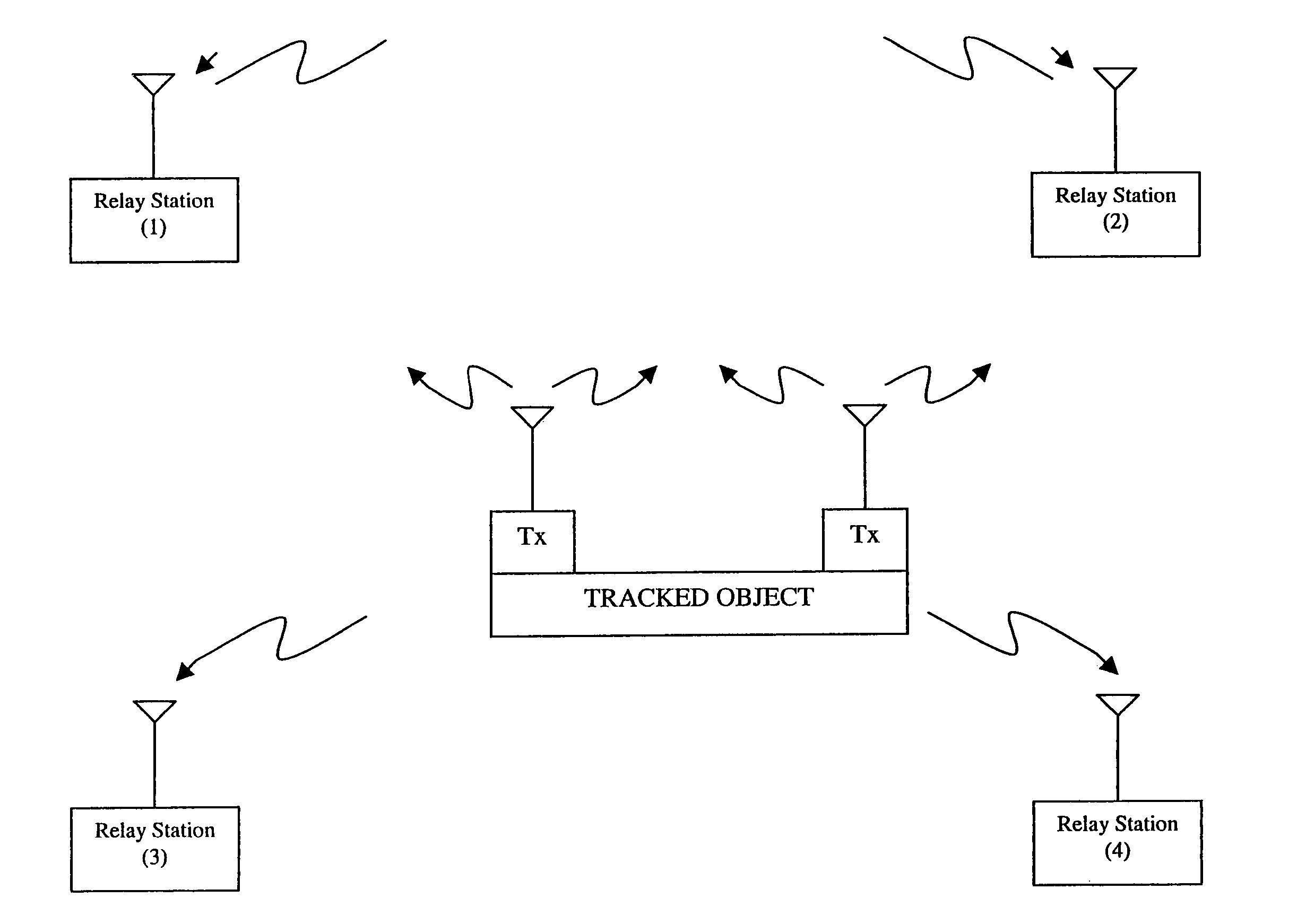
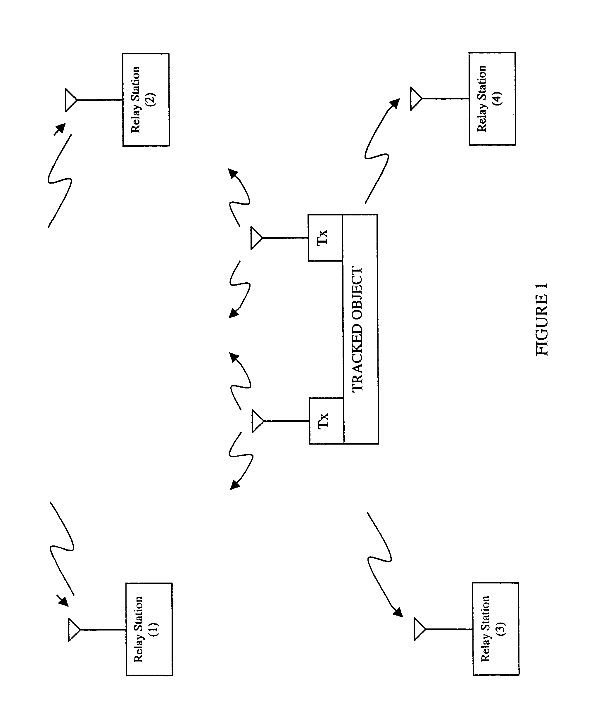
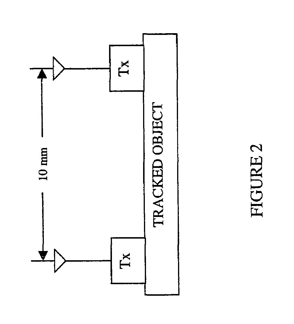
  • Application Information

AI Technical Summary

Benefits of technology

The invention is a device that sends out radio signals to be tracked in a position tracking system. The device has two antennas that send signals on alternating days, and the system uses code-division multiplexing to detect the signals from each antenna separately. By measuring the time difference of arrival of the signals, the system can determine the position of the device. The system calculates the distance between the two antennas and compares it to the known distance to assess the accuracy of the position. This technology helps improve the accuracy of position tracking.

Problems solved by technology

Several problems may occur with this type of system.
First, nearby sources of RF energy may interfere with the clean reception of the tracked object's RF transmission.
Second, RF energy transmitted by the object to be tracked may reflect off of interfering surfaces and generate echo signals which may be received by the receiver and distort the true, direct path arrival time.
The latter issue is know as multipath interference and may reduce system accuracy.

Method used


Image

  • Radio signal transmitter with multiple antennas for improved position detection
  • Radio signal transmitter with multiple antennas for improved position detection
  • Radio signal transmitter with multiple antennas for improved position detection

Examples


Embodiment Construction

[0009]One method of dealing with multipath interference is to increase the number of receivers in the system. By increasing the number, we introduce redundancy and also increase the possibility that at least some of the receivers are not receiving multipath interference. While this is a promising technique, it is also necessary to develop a method of reliably determining which of the receivers are compromised by multipath interference so that those receivers can be ignored in the subsequent position calculation. This application describes a modification of the transmitting device that provides a method of determining if a receiver has been compromised by multipath interference.

[0010]The invention involves modification of a traditional RF transmitter to include at least two transmitting antennas, spaced a fixed, known distance apart. The transmitter also incorporates a switch that will allow the output of the transmitter to be directed to either of the two antennas at any given time....


PUM


Abstract

A radio frequency (RF) signal transmission device (the “device”) is used as a tracked target in a position tracking system (the “system”). In the preferred embodiments, the device's position is determined by analyzing the time difference of arrival of the device's RF signals received at multiple receivers which are part of the system. The device has two antennas spaced a known distance apart and the device alternately transmits on these antennas or can use code-division multiplexing for individual antenna's signal detection. The system detects the position of both antennas at their respective phase center and determines the distance between the two calculated antenna positions. By comparing the calculated distance to actual known distance the system can assess the quality of the calculated positions.

Description

REFERENCE TO RELATED APPLICATION[0001]This application claims priority from U.S. Provisional Patent Application Ser. No. 60 / 612,941, filed Sep. 24, 2004, the entire content of which is incorporated herein by reference.FIELD OF THE INVENTION[0002]This invention relates generally to wireless tracking systems and, in particular, to a radio signal transmitter with multiple antenna for improved position detection.BACKGROUND OF THE INVENTION[0003]In many applications it is desirable to track, in a non-contact manner, the position of an object as it moves through 3-dimensional space. One method of accomplishing this is to embed an RF transmitter in the object to be tracked. Multiple RF receivers, positioned at known locations, capture the transmitted signal from the object to be tracked. Because the RF energy propagates at a known velocity, the differences in arrival time of the signal at any one pair of the receivers can be used to determine the possible positions of the tracked object in...

Claims


Application Information

Patent Timeline
Patent Type & Authority Patents(United States)
IPC IPC(8): G01S3/02
CPCG01S5/06G01S5/0215G01S5/0218
Inventor HILL, EDWARD L.
Owner POSITION IMAGING
Learn More