Advanced geometry of skew and straight bevel gears produced by forging

a technology of skew and straight bevel gears, which is applied in the direction of hoisting equipment, transportation and packaging, and other domestic objects, can solve the problems of unfavorable cutting gear manufacturing, inevitable vibration and noise of gear drives, and the area of contact being transferred to the edges of teeth, so as to increase production costs and avoid the effect of costing

a technology of skew and straight bevel gears, which is applied in the direction of hoisting equipment, transportation and packaging, and other domestic objects, can solve the problems of unfavorable cutting gear manufacturing, inevitable vibration and noise of gear drives, and the area of contact being transferred to the edges of teeth, so as to increase production costs and avoid the effect of costing

US7191521B2Inactive Publication Date: 2007-03-20AMERICAN AXLE & MFG

Image

  • Advanced geometry of skew and straight bevel gears produced by forging
  • Advanced geometry of skew and straight bevel gears produced by forging
  • Advanced geometry of skew and straight bevel gears produced by forging

Examples


first embodiment

[0034]In the first embodiment, shown in FIG. 8, the theoretical lines of contact on the tooth surface of the pinion and the gear are modified after generation of the tooth surfaces using the method described above. The family of theoretical lines of contact on the pinion or gear tooth surface is designated by L1. The modified line is designated as L1*. The deviation of L1* from L1 satisfies the following conditions: the magnitude of deviation is determined by a parabolic function wherein the deviation at point M is equal to zero, and it is accomplished along normal N to the tooth surface. The deviation described above creates a path of contact on the mating tooth surfaces consisting of a locus of points M, located in the center of the tooth surfaces, wherein the deviation is equal to zero. The actual contact is spread at each point over an elliptical area centered around the locus of points M due to elastic deformation of the mating tooth surfaces, as shown in FIG. 9.

second embodiment

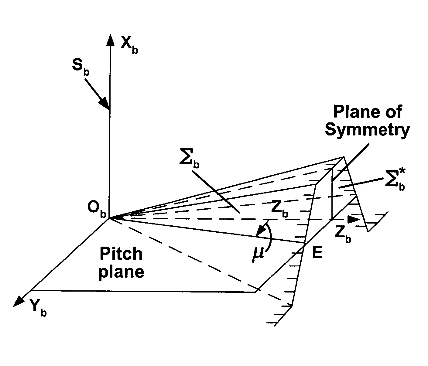
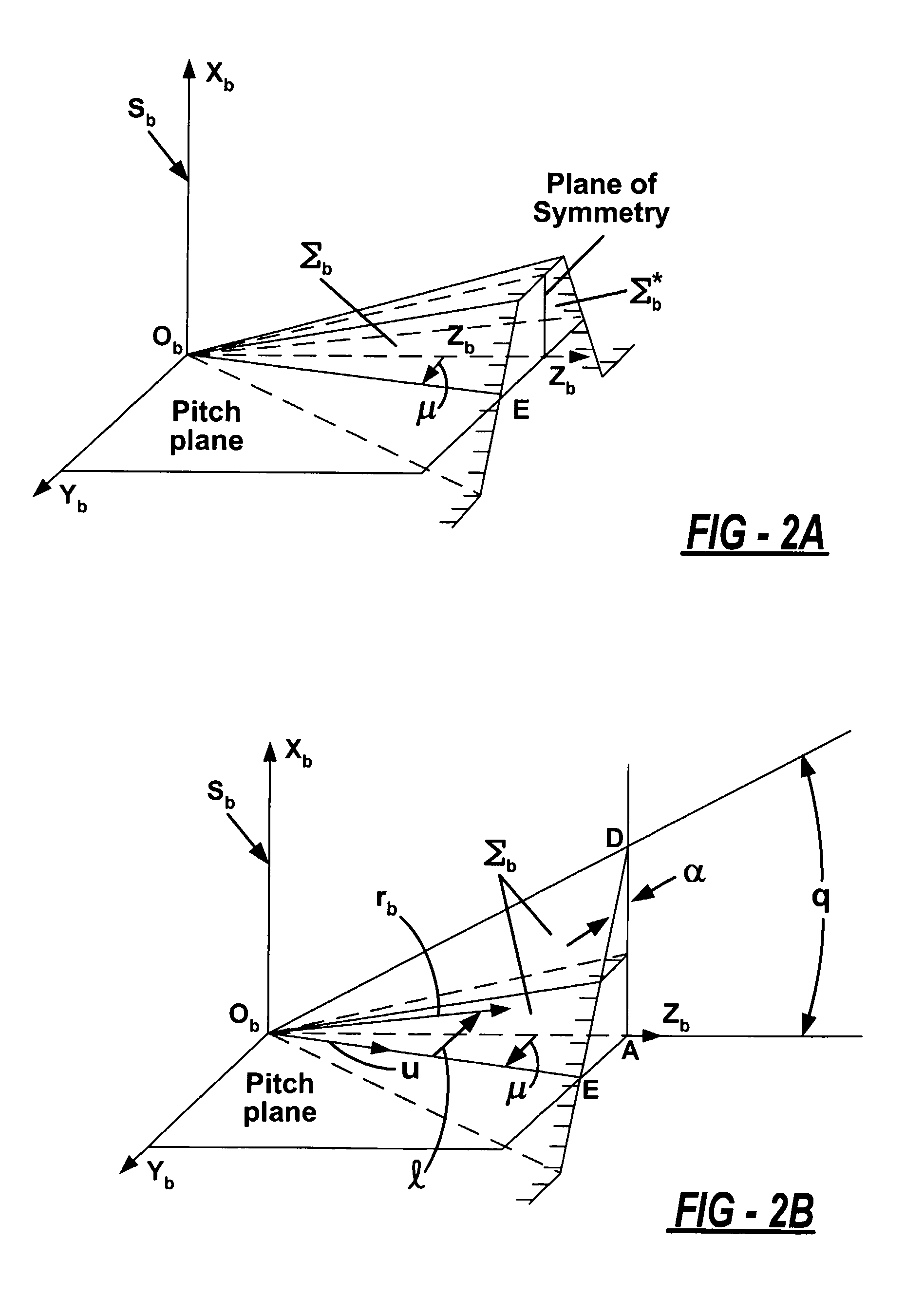
[0035]In the second embodiment, localization of bearing contact is achieved using two crown gear generating surfaces that generate pinion and gear tooth surfaces separately. One of the generating surfaces is a plane and the other generating surface is a parabolic cylinder, as shown in FIG. 10. The two generating surfaces replace the generating surfaces Σb and Σ*b in FIGS. 2(a) and 2(b). The line of tangency of the parabolic cylinder and the plane is the path of contact on the generating surface. The gear and pinion are designed using the method described above wherein the generating parabolic cylinder generates, as it rotates, a parabolic tooth surface that localizes the bearing contact when the gear and pinion are meshed.

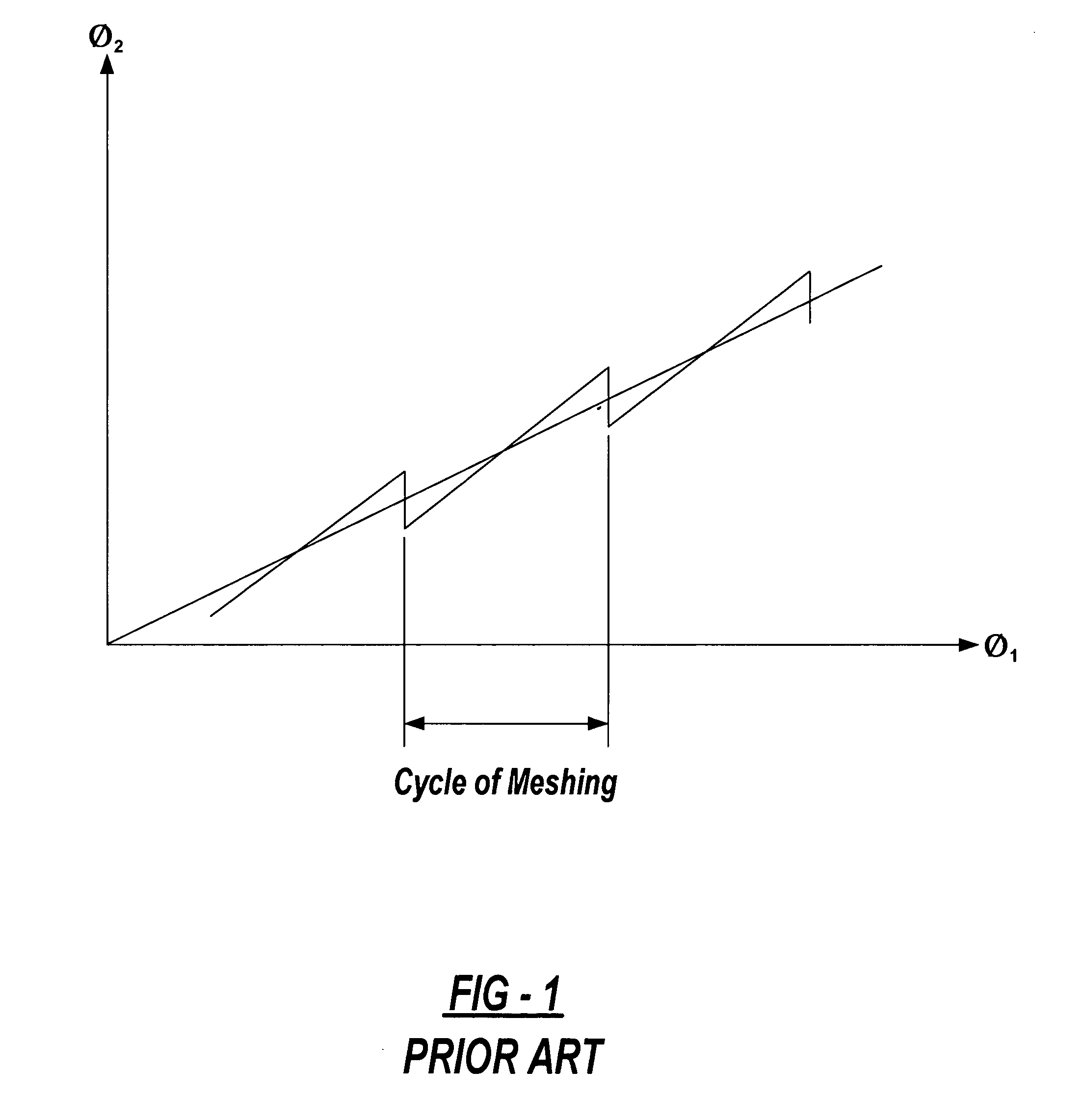
[0036]This advanced geometry enables the use of a pre-designed parabolic function that absorbs linear functions of transmission errors caused by misalignment. This transmission function φ2(φ1) is represented as the sum of a linear function and a parabolic function ...


PUM

PropertyMeasurementUnit
transmission erroraaaaaaaaaa
transmissionaaaaaaaaaa
pitch cone angleaaaaaaaaaa

Abstract

The present invention provides for bevel gears having a localized and stable bearing contact. The localization of bearing contact is achieved by substitution of flat tooth surfaces with parabolic tooth surfaces. This is accomplished by either modifying line-contact directly or by using a generating parabolic cylinder during generation of the tooth surfaces. The actual contact area is spread over an ellipse centered around an instantaneous theoretical point of contact at the apex of the parabolic tooth surface. This localized bearing contact reduces the shift of the bearing due to assembly and manufacturing errors, thereby providing a more durable and quieter gear. Furthermore, the geometry of the gear enables creation of dies from which the gear may be forged. Transmission errors are modeled using a pre-designed parabolic function that coincides with the parabolic tooth surface design of the present invention.

Description

FIELD OF THE INVENTION[0001]The present invention relates to the design of the geometry for skew and straight bevel gears produced by forging.BACKGROUND OF THE INVENTION[0002]In the past, skew and straight bevel gears have been designed to have line-contact between a gear and pinion. Here, the individual teeth of the gear and pinion interact with one another along lines of contact that shift along the face of the teeth as the gear and pinion rotate. However, errors in assembly or manufacturing, such as misalignment of the gear and pinion, can lead to the area of contact being transferred to the edges of the teeth. A transmission function φ2(φ1) of misaligned prior art gears is illustrated in FIG. 1. Angles φ1 and φ2 of transmission function φ2(φ1) represent angles of rotation of a prior art gear and pinion. Function φ2(φ1) exists as a sum of a linear function and a discontinuous almost linear function of transmission errors caused by errors of alignment. See “Gear Geometry and Appli...

Claims


Application Information

Patent Timeline
20 Mar 2007
Publication
US7191521B2
IPC
F16H55/08; B21K1/30
CPC
B21K1/30; F16H55/0853; F16H55/0886; Y10T74/19949; Y10T74/19972; Y10T29/49467; F16H55/08
Inventors
LITVIN, FAYDOR L.; ZHAO, XIANGSHUN