Optical device and projector

a technology of optical modulator and projector, which is applied in the direction of lighting and heating equipment, instruments, and domestic cooling equipment, can solve the problems of imposing extra burden on users or manufacturers, difficult to effectively cool the optical modulator, and small difference between optical modulator and cooling fluid, etc., and achieves the effect of increasing the maintainability of the projector and replenishing the cooling fluid with the accumulation section

Active Publication Date: 2007-03-20
SEIKO EPSON CORP
View PDF5 Cites 7 Cited by
  • Summary
  • Abstract
  • Description
  • Claims
  • Application Information

AI Technical Summary

Benefits of technology

[0014]An object of the present invention is to provide an optical device capable of effectively cooling an optical modulator using a cooling fluid and in which the replenishment of the cooling fluid can easily be performed, and a projector.

Problems solved by technology

Accordingly, the temperature difference between the optical modulator and cooling fluid becomes smaller, making it difficult to effectively cool the optical modulator.
It is necessary to request the manufacturer of the product to perform the replenishment of the cooling fluid in the case where the volume of the cooling fluid has fallen outside the guaranteed operating range after use during a predetermined period, imposing extra burden on the user or manufacturer.
Further, when the user of the product himself or herself replenishes the liquid cooling system with a new cooling fluid, there is a possibility that the cooling fluid leaks into the inside of the product.

Method used


Image

  • Optical device and projector
  • Optical device and projector
  • Optical device and projector

Examples


first embodiment

[First Embodiment]

[0075]A first embodiment of the present invention will be described below with reference to the accompanying drawings.

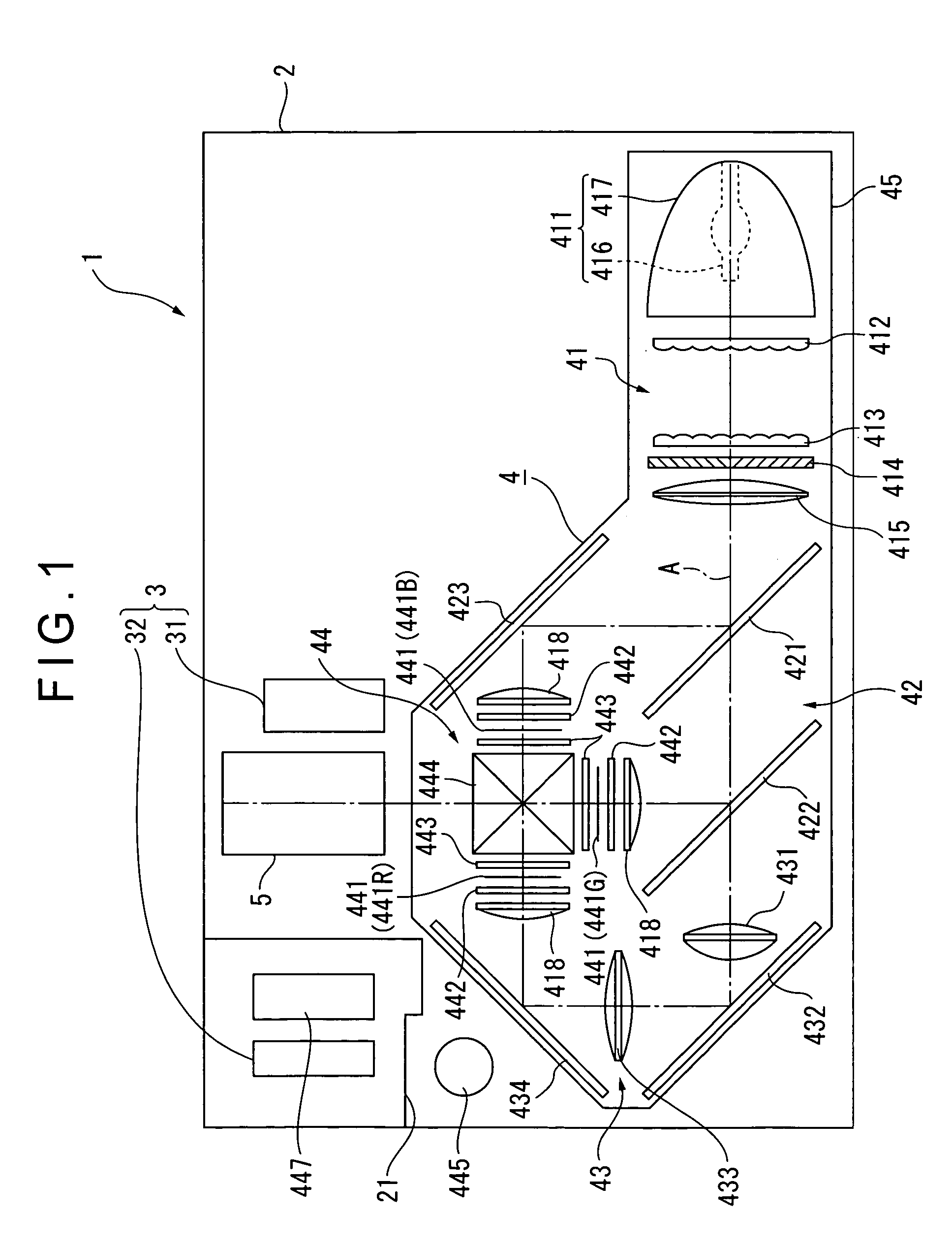
[0076]FIG. 1 is a view schematically showing a configuration of a projector 1.

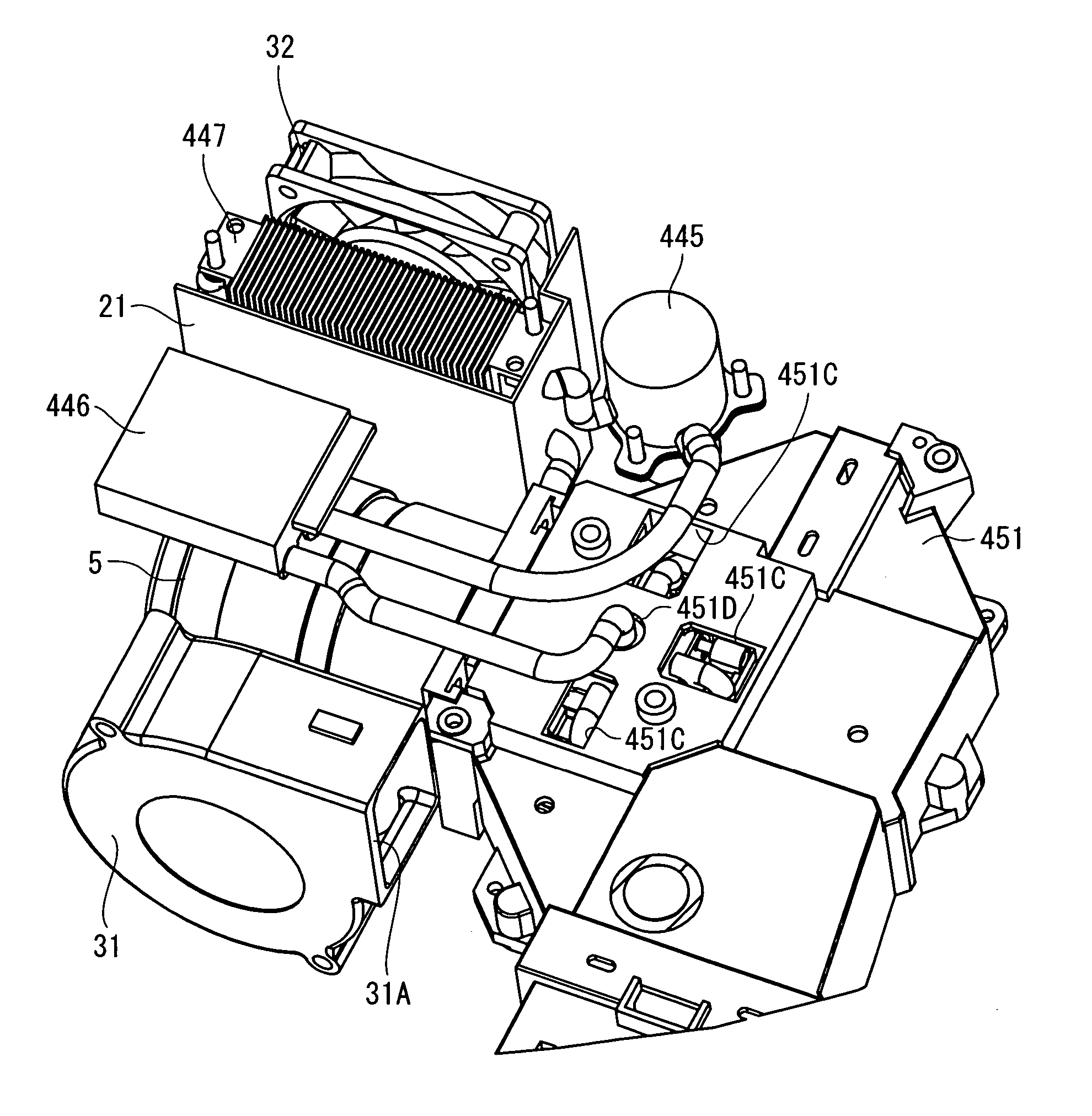
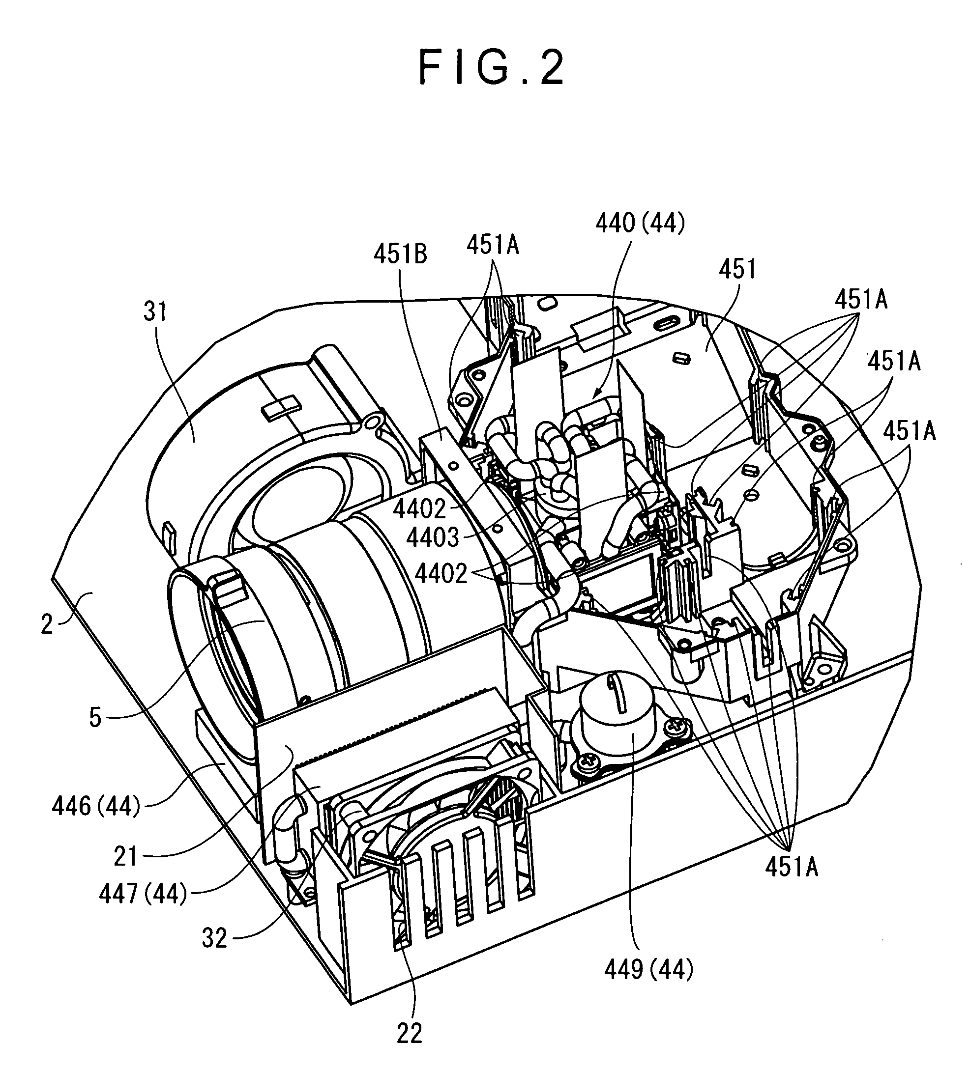
[0077]The projector 1 modulates a light beam emitted from a light source in accordance with image information to form an optical image and projects the formed optical image on a screen in an enlarged manner. The projector 1 includes an outer case 2 serving as an outer casing, a cooling unit 3, an optical unit 4, and a projection lens 5 serving as a projection optical device.

[0078]In the outer case 2 of FIG. 1, although not shown, a power block, a lamp drive circuit and the like are arranged in the space other than the portions occupied by the cooling unit 3, optical unit 4, and projection lens 5.

[0079]The outer case 2 is formed of synthetic resin and the like and is formed in substantially a rectangular solid shape as a whole inside which the cooling unit 3, optical unit4,...

second embodiment

[Second Embodiment]

[0214]A second embodiment of the present invention will next be described with reference to the accompanying drawings.

[0215]In the following description, the same reference numerals as those in the first embodiment denote the same structures and components as those in the first embodiment, and the detailed descriptions thereof are omitted or simplified.

[0216]In the first embodiment, the outlet valve 4491B of the replenishment tank 449 is moved by the valve guide section 4454C of the main tank 445 to open the outlet hole 4491A in the closed state. The replenishment tank 449 has no mechanism to allow the position of the outlet valve 4491B to be set back to the position at which the outlet hole 4491A is in a closed state from the open position of the outlet hole 4491A.

[0217]On the other hand, in the second embodiment, a replenishment tank 549 has a mechanism to allow the position of an outlet valve 5491B to be set back to the position at which a cooling fluid outlet ...

third embodiment

[Third Embodiment]

[0232]A third embodiment of the present invention will next be described with reference to the accompanying drawings.

[0233]In the following description, the same reference numerals as those in the first embodiment denote the same structures and components as those in the first embodiment, and the detailed descriptions thereof are omitted or simplified.

[0234]In the first embodiment described above, the replenishment tank 449 is attached to the main tank 445 when the main tank 445 needs to be replenished with a cooling fluid.

[0235]On the other hand, in the third embodiment, a cooling fluid inlet section 6454 is formed so that a main tank 645 can be replenished with a cooling fluid, which eliminates the need for the replenishment tank 449. It is assumed that the configurations of the components other than the main tank 645 are the same as those in the first embodiment.

[0236]FIG. 14 is a perspective view showing a structure of the main tank 645 according to the third e...


PUM

PropertyMeasurementUnit
heataaaaaaaaaa
volumeaaaaaaaaaa
optical imageaaaaaaaaaa

Abstract

An optical device (44) includes: a optical modulator holder (4402) that has inside thereof a cooling chamber in which a cooling fluid is encapsulated, and holds a optical modulator in such a manner that heat can be transferred between the optical modulator holder and the cooling fluid within the cooling chamber; a plurality of fluid circulation members (448) that are connected to the cooling chamber of the optical modulator holder (4402) for mutual communication to guide the cooling fluid outside the cooling chamber and guide the cooling fluid inside the cooling chamber, again; and a main tank (445) that is arranged in the flow path of the cooling fluid in the plurality of fluid circulation members (448) and accumulates the cooling fluid. The main tank (445) has a cooling fluid inlet section for allowing the main tank (445) to be replenished with the cooling fluid.

Description

BACKGROUND OF THE INVENTION[0001]1. Field of the Invention[0002]The present invention relates to an optical device and a projector.[0003]2. Description of Related Art[0004]Conventionally, a projector provided with a plurality of light modulation devices that modulate a light beam emitted from a light source in accordance with image information to form an optical image, a color synthesis optical device that synthesizes and emits the light beam that has been modulated in each light modulation device, and a projection optical device that projects the light beam that has been synthesized in the color synthesis optical device in an enlarged manner has been known.[0005]As the light modulation device, e.g., an optical modulator of an active matrix drive type in which an electro-optic material such as a liquid crystal is encapsulated between a pair of substrates is adopted in general. More specifically, the pair of substrates that constitute the optical modulator includes a drive substrate ...

Claims


Application Information

Patent Timeline
Patent Type & Authority Patents(United States)
IPC IPC(8): G03B21/16G03B21/18G03B21/26G02F1/13F25B43/04F25D9/00F25D17/02G02B26/00G02F1/00G02F1/133G02F1/1333G03B21/00G03B21/14H04N9/31
CPCG02F1/133385H04N9/3144
Inventor FUJIMORI, MOTOYUKIMURATA, MASAMI
Owner SEIKO EPSON CORP
Why Eureka
Try Eureka