Bullnose step turbine nozzle

a turbine nozzle and step turbine technology, applied in the direction of machines/engines, liquid fuel engines, supersonic fluid pumps, etc., can solve the problems of random differences in the relative positions of adjacent components, substantial thermal expansion and contraction, and correspondingly affecting the size of the tip clearan

Inactive Publication Date: 2007-03-27
GENERAL ELECTRIC CO
View PDF8 Cites 26 Cited by
  • Summary
  • Abstract
  • Description
  • Claims
  • Application Information

AI Technical Summary

Problems solved by technology

Since the first stage nozzle of the HPT first receives the hottest combustion gases from the combustor it is subject to substantial thermal expansion and contraction during operation.
Since the turbine shrouds are suspended around the blade tips, relative expansion and contraction therebetween is permitted which correspondingly affects the size of the tip clearance.
However, the aerodynamic contours of the turbine nozzles and rotor stages are nevertheless subject to the small manufacturing tolerances of the individual components, and the small assembly tolerances when the components are mounted in the engine.
These tolerances necessarily introduce random differences in the relative positions of adjacent components due to the independent assembly and mounting of these components.
An up-step between nozzle segments will correspondingly obstruct combustion gas flow and reduce performance as well as locally heat the protruding step.
A down-step is more desirable since it is subject to less heating from the combustion gases than an up-step, but nevertheless introduces a surface discontinuity which decreases efficiency.
Furthermore, since the combustion gas streamlines change direction as they flow over an individual splitline between the leading and trailing edges of the vanes, a desirable down-step at either the leading or trailing edges of the vanes will necessarily result in an undesirable up-step at the opposite side of the segment for nominally flush band designs.
However, the use of chamfers and height changes in the platforms or bands correspondingly affects aerodynamic performance of the stator and rotor stages, and a compromise in design must be made for minimizing overall losses.

Method used


Image

  • Bullnose step turbine nozzle
  • Bullnose step turbine nozzle
  • Bullnose step turbine nozzle

Examples


Embodiment Construction

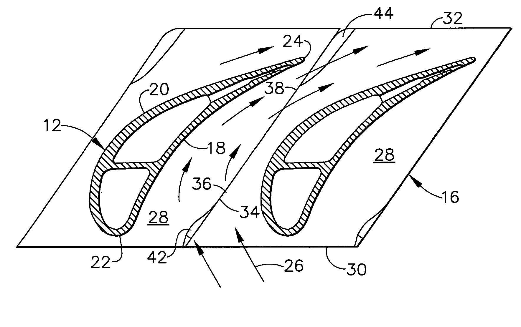
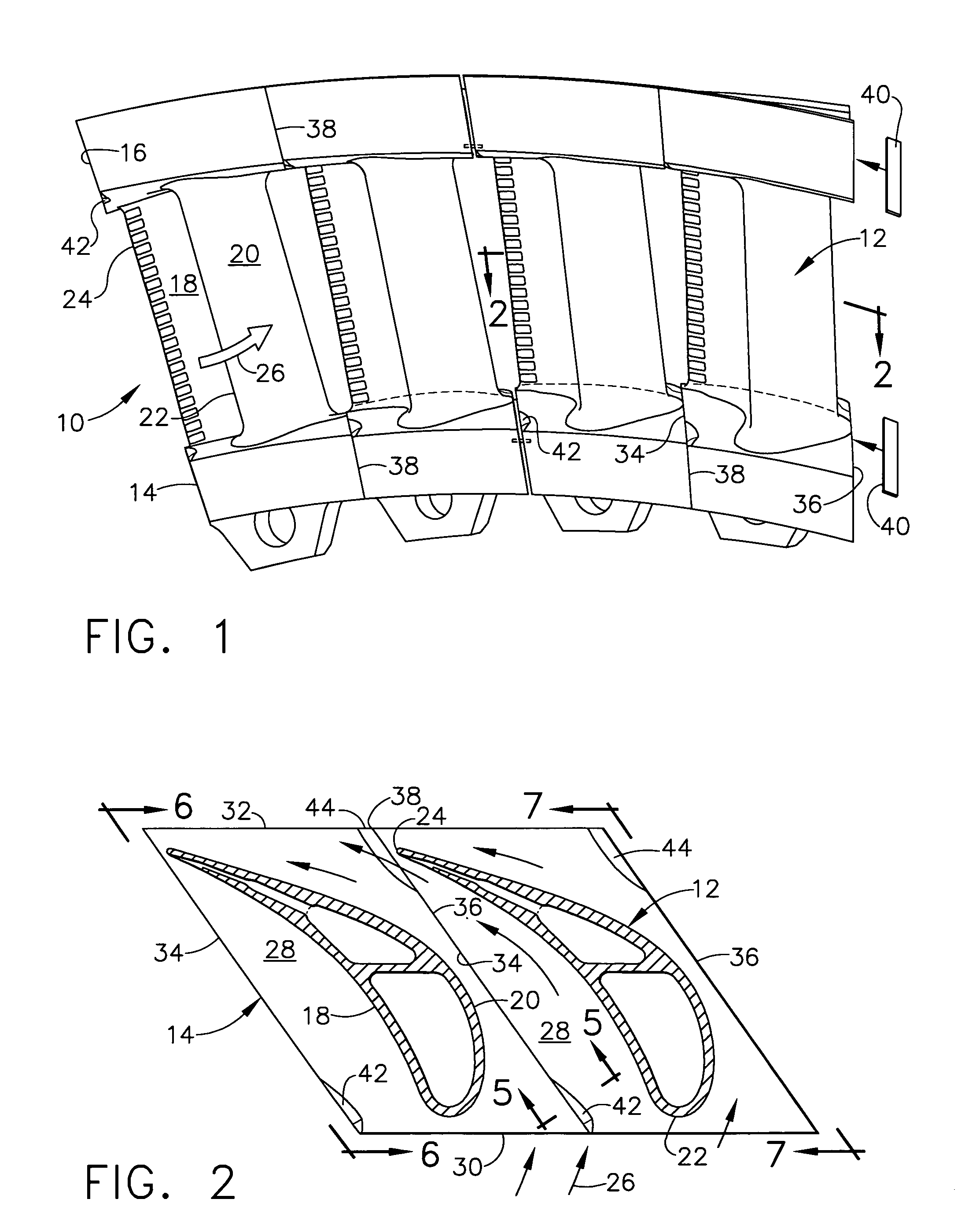
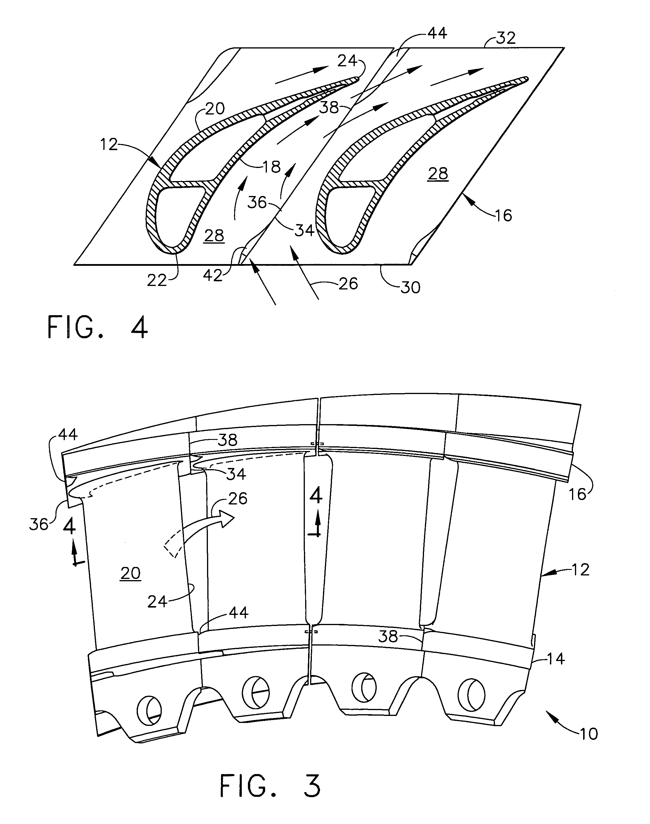
[0034]Illustrated in FIG. 1 is an arcuate portion of an annular first stage high pressure turbine nozzle 10 for a gas turbine engine. The nozzle is axisymmetric about the axial centerline axis of the engine and includes a plurality of hollow stator vanes 12 integrally joined at radially opposite root ends to radially inner and outer arcuate bands 14,16. For example, the individual vanes 12 may be cast with their corresponding inner and outer bands in a unitary configuration thereof.

[0035]As additionally illustrated in FIG. 2, each of the vanes 12 has an aerodynamic airfoil configuration with a generally concave pressure side 18, and a circumferentially or laterally opposite, generally convex suction side 20. The two sides extend axially in chord between opposite leading and trailing edges 22,24 which extend the full radial span of each vane airfoil between the two bands 14,16.

[0036]The individual vanes themselves may have any conventional configuration and typically include internal...


PUM


Abstract

A turbine airfoil includes opposite pressure and suction sides extending in span from a flowpath surface. The flowpath surface has chordally opposite forward and aft edges and laterally opposite first and second endfaces corresponding with the airfoil pressure and suction sides. The flowpath surface joins the first endface at the forward edge in a forward bullnose and joins the second endface at the aft edge in an aft bullnose, with the bullnoses varying in radius from the opposite edges.

Description

BACKGROUND OF THE INVENTION[0001]The present invention relates generally to gas turbine engines, and, more specifically, to turbine flowpaths therein.[0002]In a gas turbine engine, air is pressurized in a compressor and mixed with fuel in a combustor for generating hot combustion gases. Energy is extracted from the hot gases in turbine stages for powering the compressor and producing output work in driving an upstream fan in a turbofan aircraft engine application, or in powering an external drive shaft for marine and industrial applications.[0003]A high pressure turbine (HPT) immediately follows the combustor outlet and includes a stationary turbine nozzle followed in turn by a row of turbine rotor blades extending radially outwardly from the perimeter of a supporting disk. The HPT may include more than one stage and drives the rotor supporting the compressor rotor blades.[0004]A low pressure turbine (LPT) follows the HPT and typically includes several stages of turbine nozzles and ...

Claims


Application Information

Patent Timeline
Patent Type & Authority Patents(United States)
IPC IPC(8): F03B1/04F03B3/16
CPCF01D5/143F01D5/145F01D9/041F01D25/246F01D11/005F05D2250/19Y02T50/673Y02T50/60
Inventor LU, WENFENGLEE, CHING-PANGPALMER, NICHOLAS CHARLES
Owner GENERAL ELECTRIC CO
Why Eureka
Try Eureka