
Dual-chamber liquid receiving and containing device

a liquid receiving and containing device technology, applied in medical science, vaccination/ovulation diagnostics, packaging, etc., can solve the problems of contaminated and unsuitable urinalysis, high incidence of false positive diagnosis, and inability to strictly follow cleaning procedures, so as to ensure the over-center locking of the web and the device body footprin

Inactive Publication Date: 2007-03-27
BIOMARKETING SERVICES M SDN BHD
View PDF33 Cites 19 Cited by
  • Summary
  • Abstract
  • Description
  • Claims
  • Application Information

AI Technical Summary

Benefits of technology

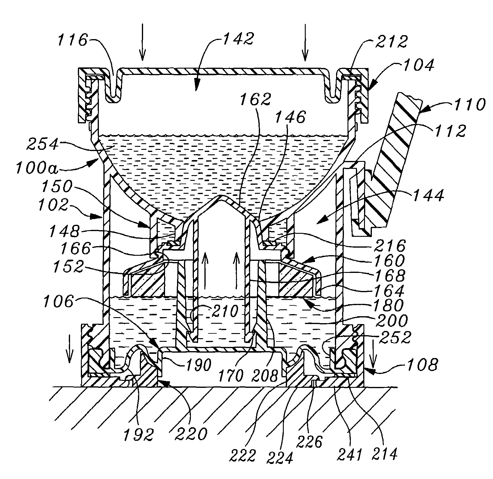
[0014]It is preferred that the stopper be formed having an outwardly flared circular skirt region. A ring-shaped float having a height selected to provide the predetermined liquid level in the lower chamber is preferably disposed beneath the stopper circular skirt region for providing floating stability to the stopper.
[0025]In a further variation dual-chamber device, an aqueous liquid-activated adhesive is applied to the transverse wall around the orifice and a removable spacer is disposed between the stopper and the orifice to prevent device pre-use adhering of the stopper into the orifice. As liquid is introduced into the lower chamber so as to float the stopper upwardly into the orifice, the adhesive is activated, thereby positively locking the stopper into the orifice so as to assure that liquid does not leak past the stopper between the upper and lower chambers.

Problems solved by technology

Generally, these tedious and highly intimidating cleaning procedures are not strictly followed due to ignorance or non-acceptance, especially by younger female patients.
Added to the facts of inadequacy in the cleaning process and heretofore unavailability of a competent collection system capable of capturing and isolate the mid-stream urinary specimen, a high incidences of “false positive” diagnostic results has always remained a pit-fall in clinical urinary tract infection management.
In females, in particular, this fore-stream urine, while flowing through a poorly cleaned external urogenital tract, is always regarded as contaminated and unsuitable for urinalysis, especially for microbiological or bacteriological examination.
More often than not, the fore-stream urine contaminants produce a high incidence of false positive lab test results that are unfortunately derived from external contaminants located around the external urogenital anatomic parts.
When this unintentionally contaminated fore-stream urine, while “rinsing” through the patient's urogenital pathway, is collected in a conventional single chamber collection container and then mixes with the later cleaner, mid-stream sample, such badly mixed mid-stream sample is regarded as unsuitable or unacceptable for lab diagnosis procedures.
A problem associated with such mid-stream urine collection is the assuring of an appropriate cleansing fore-stream urine flow (which is not used for the bacteriological analysis).
If the fore-stream urine flow is too small, it will result in inadequate rinsing of the urogenital pathway, and the subsequently collected mid-stream urine flow may be contaminated, thereby adversely affecting the bacterial urinalysis.
On the other hand, if the fore-stream urine flow is too large, the patient may produce a mid-stream urine flow quantitatively insufficient for urinalysis purposes (typically 6 ml to 12 ml required).
In such a procedure, the amount of discharged fore-stream urine is usually difficult to control for females, and if too small, may result in a contaminated mid-stream urine flow and if too large may result in too small a mid-stream urine flow for accurate biological analysis.
Moreover, such a procedure involves the patient uninterrupting her (or his) urine flow to collect the mid-stream flow—something that may be difficult for collecting the mid-stream urine flow.
In any event, such a procedure may result in unintended, unsanitary urination onto the patient's hand and / or the urine collection container.

Method used


Image

  • Dual-chamber liquid receiving and containing device
  • Dual-chamber liquid receiving and containing device
  • Dual-chamber liquid receiving and containing device

Examples


Embodiment Construction

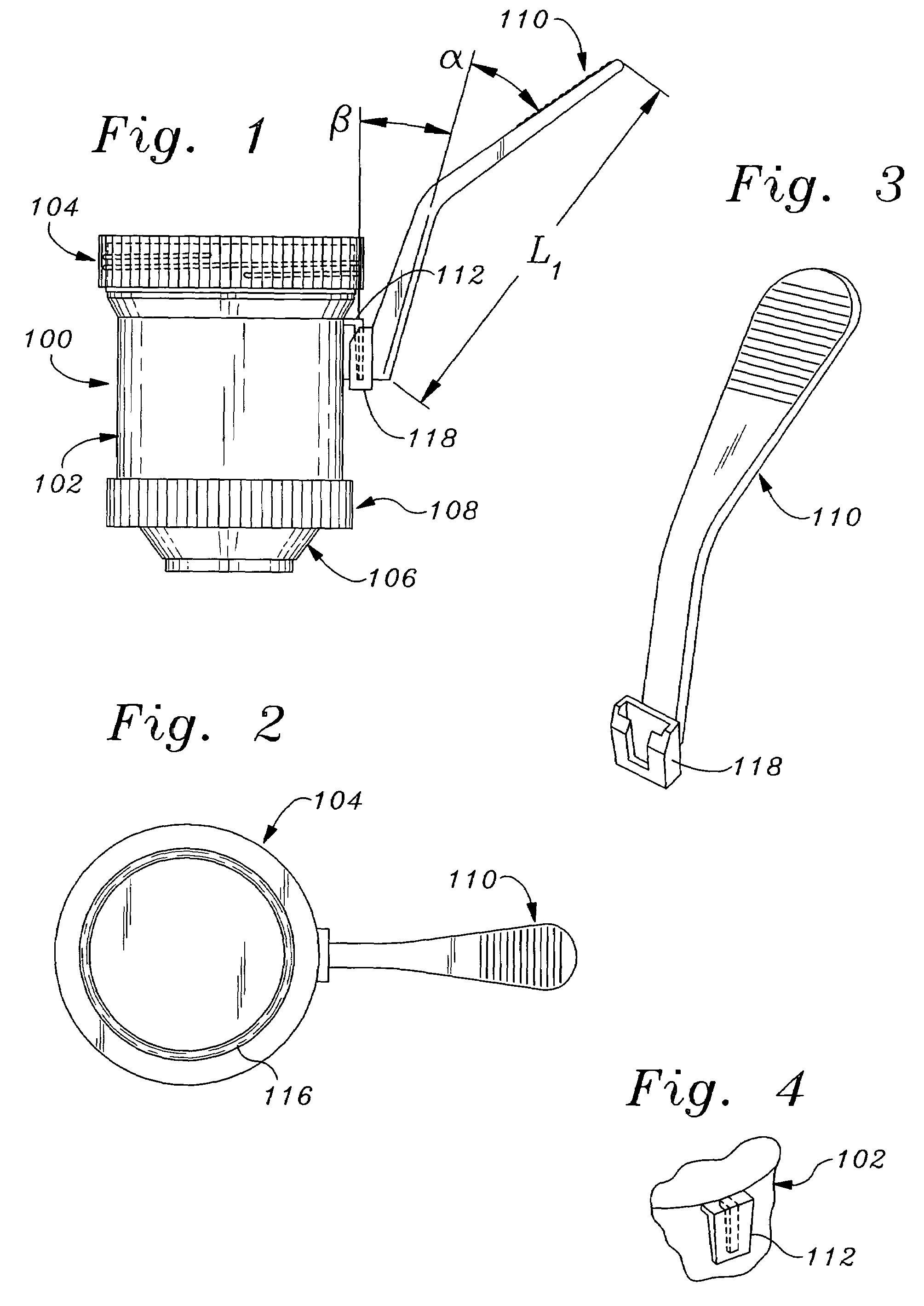
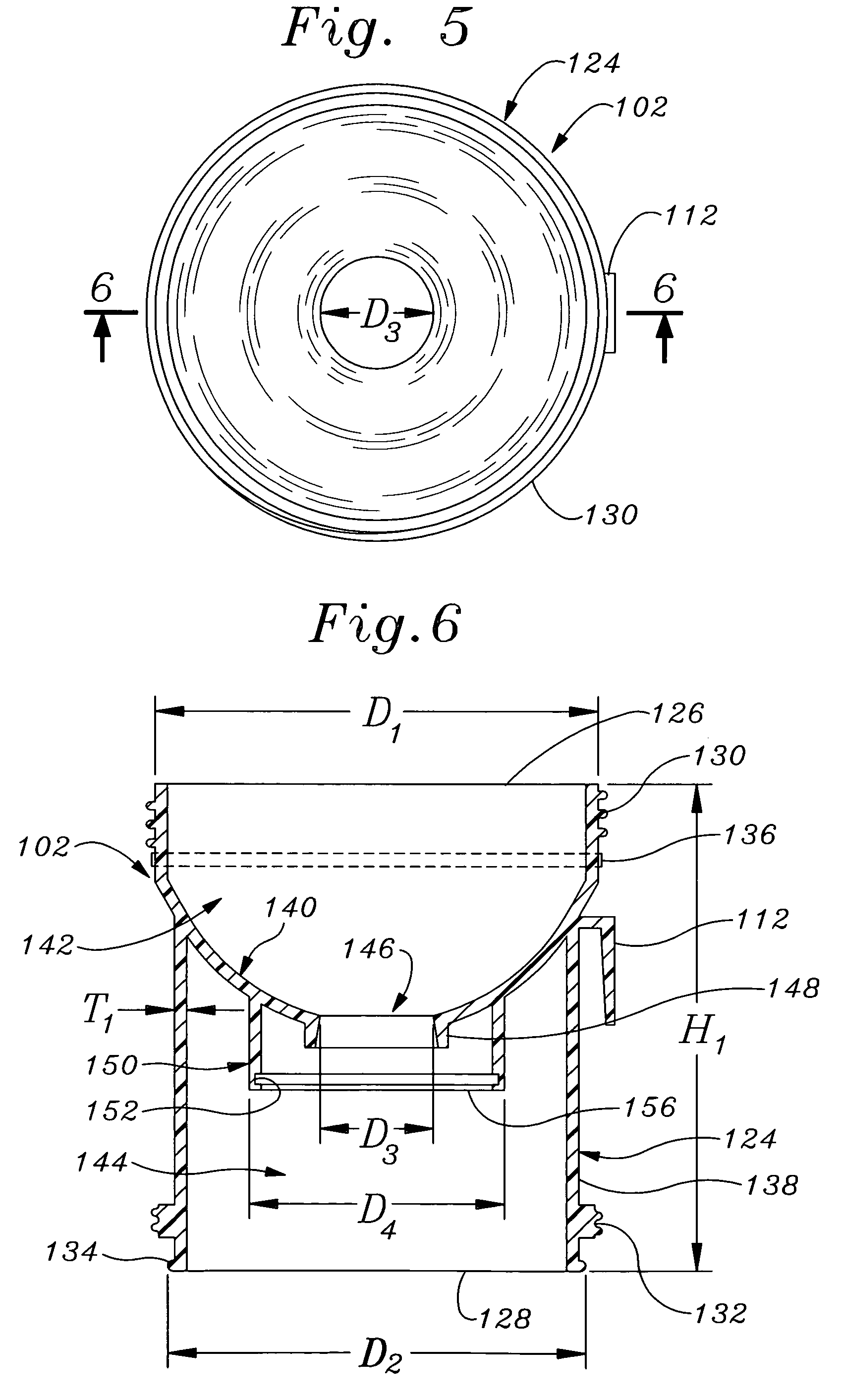
[0089]There is shown in FIG. 1 a dual-chamber, liquid receiving and containing device 100 (hereinafter, for the sake of brevity, usually referred to as the “dual-chamber device”) which may advantageously be used to receive a flow of urine from a patient and contain the urine flow as separate fore-stream and mid-stream flow portions, as described below.

[0090]Shown comprising dual-chamber device 100, as more particularly described below, are a generally cylindrical device body or liquid cup 102, a top cover or cap 104 that is detachably attached at an open upper end of the body, a bottom cover or cap 106 that is attached to an open bottom of the body, a bottom cover locking ring 108 that is threaded onto the body to secure the bottom cover to the body (as discussed below), and an angled handle 110 that is detachably attached to the body by a tapered fitting 112 projecting from upper regions of the body.

[0091]Top cover 104 is shown in FIG. 2 as having an annular device sealing recess o...


PUM


Abstract

A dual-chamber device for receiving and containing a liquid, particularly urine, employs a generally cylindrical body having a detachable top cover and an internal, transverse, funnel-shaped wall. The transverse wall has a central circular orifice and divides the body into lower and upper chambers for respectively receiving and retaining fore-stream and mid-stream urine liquid samples. A floatable orifice stopper in the lower chamber is responsive to fore-stream liquid filling the lower chamber to a predetermined level for closing the orifice, so that subsequent, mid-stream urine liquid is received into the upper chamber. An annular float beneath the orifice stopper assures proper stopper closing of the orifice. A bottom cover has an upstanding stopper pushing column and a flexible, spring-like, annular web adjacent the cover periphery. When the urine liquid has been collected in the device and the device is pushed downwardly onto the bottom cover, the web flexes, causing the bottom cover column to force the stopper tightly into the orifice, and locks over center to positively lock the stopper into the orifice to prevent leakage between the two chambers. Other mechanisms, including a urine liquid released compression spring, a urine liquid swellable hydrophilic material, a urine liquid activated effervescent tablet, magnetic elements and urine liquid activated adhesive, are disclosed for positively locking the stopper into the orifice.

Description

[0001]This application is a utility patent application converted from provisional application Ser. Nos. 60 / 483,782 and 60 / 494,773, filed respectively on Jun. 28, 2003 and Aug. 13, 2003.FIELD OF THE INVENTION[0002]The present invention relates to the general field of devices for collecting and separately containing dual samples of a liquid, more particularly to the collection and separately containing of dual samples of body fluids, and still more particularly to the collection and separate containing of dual samples of urine for analysis.BACKGROUND OF THE INVENTION[0003]Circumstances often arise wherein a desire or necessity exists for the collection and separate containment of samples of a liquid. As one example, bacterial urinalysis typically requires the collection of a flow of what is generally termed “mid-stream” urine, as described below.[0004]The best mid-stream urine specimen for bacteriologic diagnostic examination is obtained directly from a patient's urinary bladder by ca...

Claims


Application Information

Patent Timeline
Patent Type & Authority Patents(United States)
IPC IPC(8): A61B5/00B65D81/00A61B10/00
CPCA61B10/007
Inventor YONG, PETER A. K.RISPLER, MARK J.
Owner BIOMARKETING SERVICES M SDN BHD
Learn More