Embedded toroidal transformers in ceramic substrates

a technology of ceramic substrates and toroidal transformers, applied in the field of toroidal transformers, can solve the problems of coil loss, air core loss, coil loss,

Active Publication Date: 2007-03-27
HARRIS CORP
View PDF41 Cites 79 Cited by
  • Summary
  • Abstract
  • Description
  • Claims
  • Application Information

AI Technical Summary

Problems solved by technology

This type of loss results from the magnetizing and de-magnetizing of the core during normal operation of the transformer.
Coil loss is the result of resistance that exists in the winding materials.
For a particular transformer having a particular turns ratio it is well known that an air core will result in lower efficiency because it has a permeability of 1.0 (the terms permeability and permittivity as used herein should be understood to mean relative permeability and relative permittivity, respectively).
However, planar spiral transformers suffer from a serious drawback in that they do not substantially contain the magnetic field that they produce.
However, implementation of toroids in miniaturized RF circuitry has presented practical difficulties that have typically required them to be implemented as surface mount components.
Regardless of the exact design of a surface mount component, the circuit board real estate required for such components has become a significant factor contributing to the overall size of RF systems.
This is not an effective use of board real estate.
These additional steps naturally involve further expense.
Further, such techniques are poorly suited for use with other types of substrates, such as ceramic types described below.
Typically, the range of commercially available LTCC materials has been fairly limited.

Method used


Image

  • Embedded toroidal transformers in ceramic substrates
  • Embedded toroidal transformers in ceramic substrates
  • Embedded toroidal transformers in ceramic substrates

Examples


Embodiment Construction

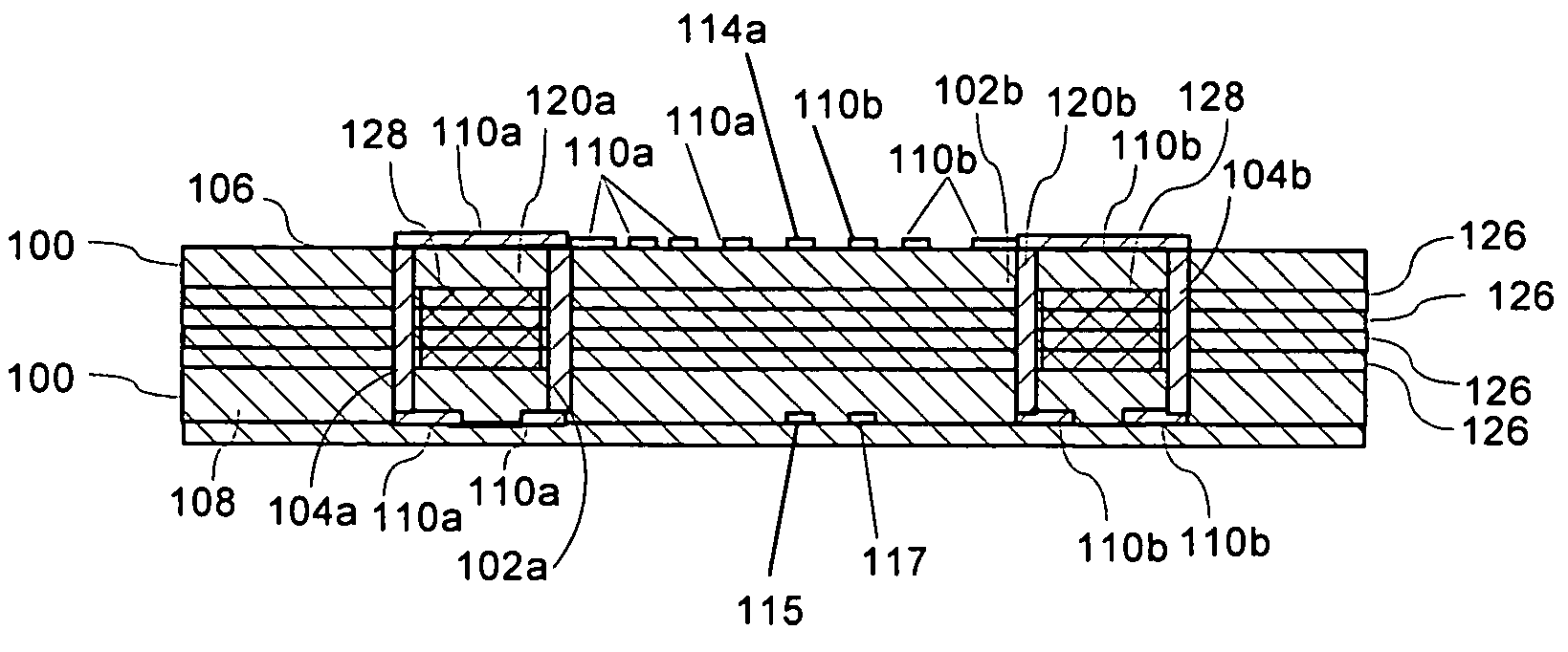
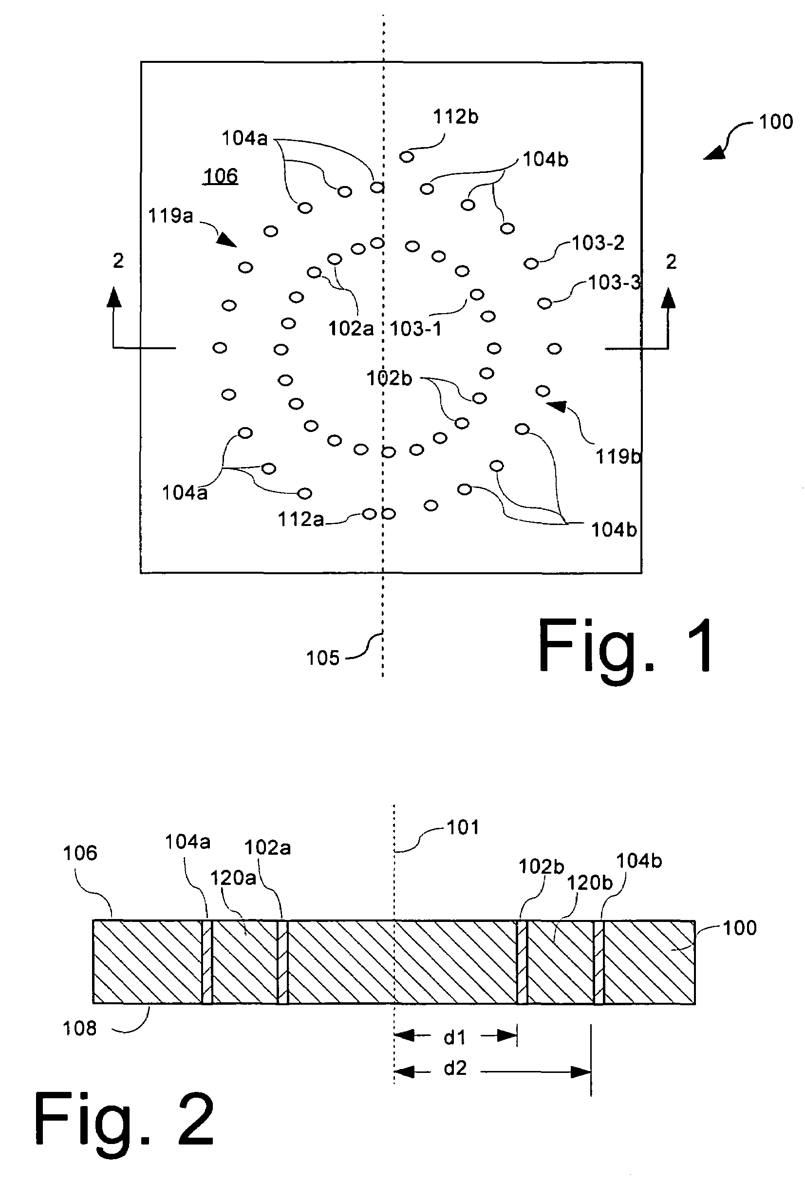
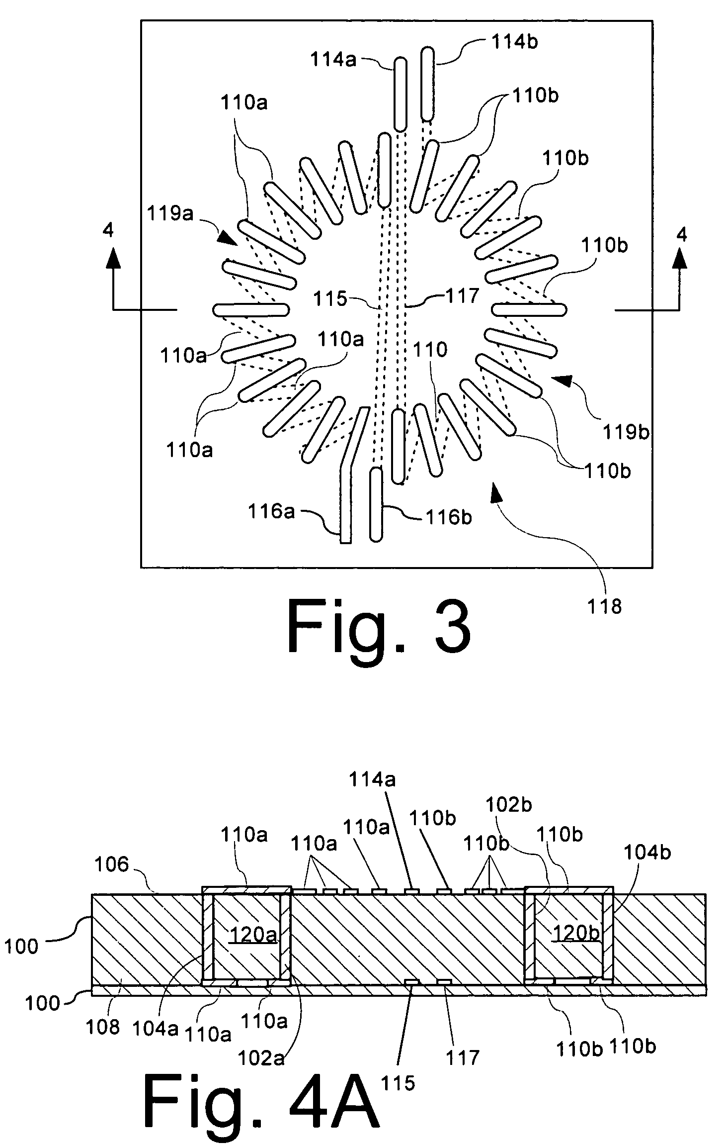
[0032]The invention concerns a toroidal transformer integrated within a ceramic substrate and a method of making same. The method shall be described in reference to FIGS. 1–4, and the flowchart in FIG. 5. The method can begin with step 502 by forming a suitably sized piece of unfired ceramic tape 100. The ceramic tape 100 can be any of a variety of commercially available glass ceramic substrates designed to be calcined at about 800° C. to 1,050° C. This class of materials is commonly referred to as low-temperature co-fired ceramics (LTCC). Such LTCC materials have a number of advantages that make them especially useful as substrates for RF systems. For example, low temperature 951 co-fire Green TapeTM from Dupont® is Au and Ag compatible, and it has a thermal coefficient of expansion (TCE) and relative strength that are suitable for many applications. Other similar types of ceramic tapes can also be used. The size of the ceramic tape can be determined by a variety of factors dependi...


PUM

PropertyMeasurementUnit
temperatureaaaaaaaaaa
angleaaaaaaaaaa
permeabilityaaaaaaaaaa

Abstract

Method for forming a transformer (118) in a ceramic substrate. The method can include the steps of forming at least one conductive coil (119a, 119b) comprising a plurality of turns about an unfired ceramic toroidal core region (120a, 120b) defined within an unfired ceramic substrate (100). The method can also include the step of co-firing the unfired ceramic toroidal core region (120a, 120b), the unfired ceramic substrate (100), and the conductive coil (119a, 119b) to form an integral ceramic substrate structure with the conductive coil at least partially embedded therein.

Description

BACKGROUND OF THE INVENTION[0001]1. Statement of the Technical Field[0002]The inventive arrangements relate generally to transformers and more particularly to toroidal transformers.[0003]2. Description of the Related Art[0004]Transformers are passive electrical devices that transform alternating or intermittent electric energy in one circuit into energy of a similar type in another circuit, commonly with altered values of voltage and current. The ratio of input voltage to output voltage in a particular transformer device is generally determined by the number of turns in the primary coil as compared to the secondary coil. There is a small loss associated with this transformation that is made up of two components. The first source of loss is referred to as “core” loss (also called no-load loss). This type of loss results from the magnetizing and de-magnetizing of the core during normal operation of the transformer. The second loss component is called coil or load loss, because the eff...

Claims


Application Information

Patent Timeline
Patent Type & Authority Patents(United States)
IPC IPC(8): H01F5/00H01F27/28H01F7/06H01F17/00H01F41/04H01L23/498H04N15/00
CPCH01F17/0033H01F41/046H01L23/49822H01L2924/09701Y10T29/4902H01L2924/0002H01L2924/3011H01L2924/00H01F5/00H01F27/00
Inventor PLESKACH, MICHAEL D.THOMSON, ANDREW J.
Owner HARRIS CORP
Why Eureka
Try Eureka