Minimum gate delay edge counter

a gate delay and edge counter technology, applied in the field of edge counters, can solve the problem of not being able to achieve a 50/50 duty cycle outpu

Active Publication Date: 2007-03-27
NAT SEMICON CORP
View PDF9 Cites 9 Cited by
  • Summary
  • Abstract
  • Description
  • Claims
  • Application Information

AI Technical Summary

Problems solved by technology

Conventional counters typically only count one type of edge (rising or falling) of the input signal, and cannot achieve a 50 / 50 duty cycle output when the divide ratio is odd.

Method used


Image

  • Minimum gate delay edge counter
  • Minimum gate delay edge counter
  • Minimum gate delay edge counter

Examples


Embodiment Construction

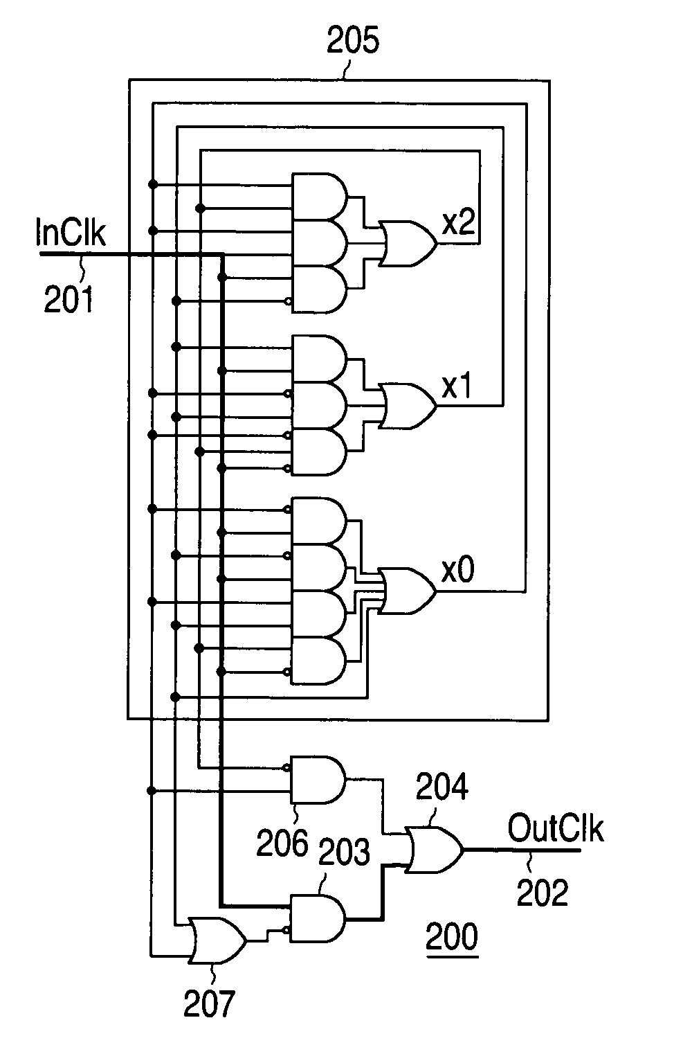
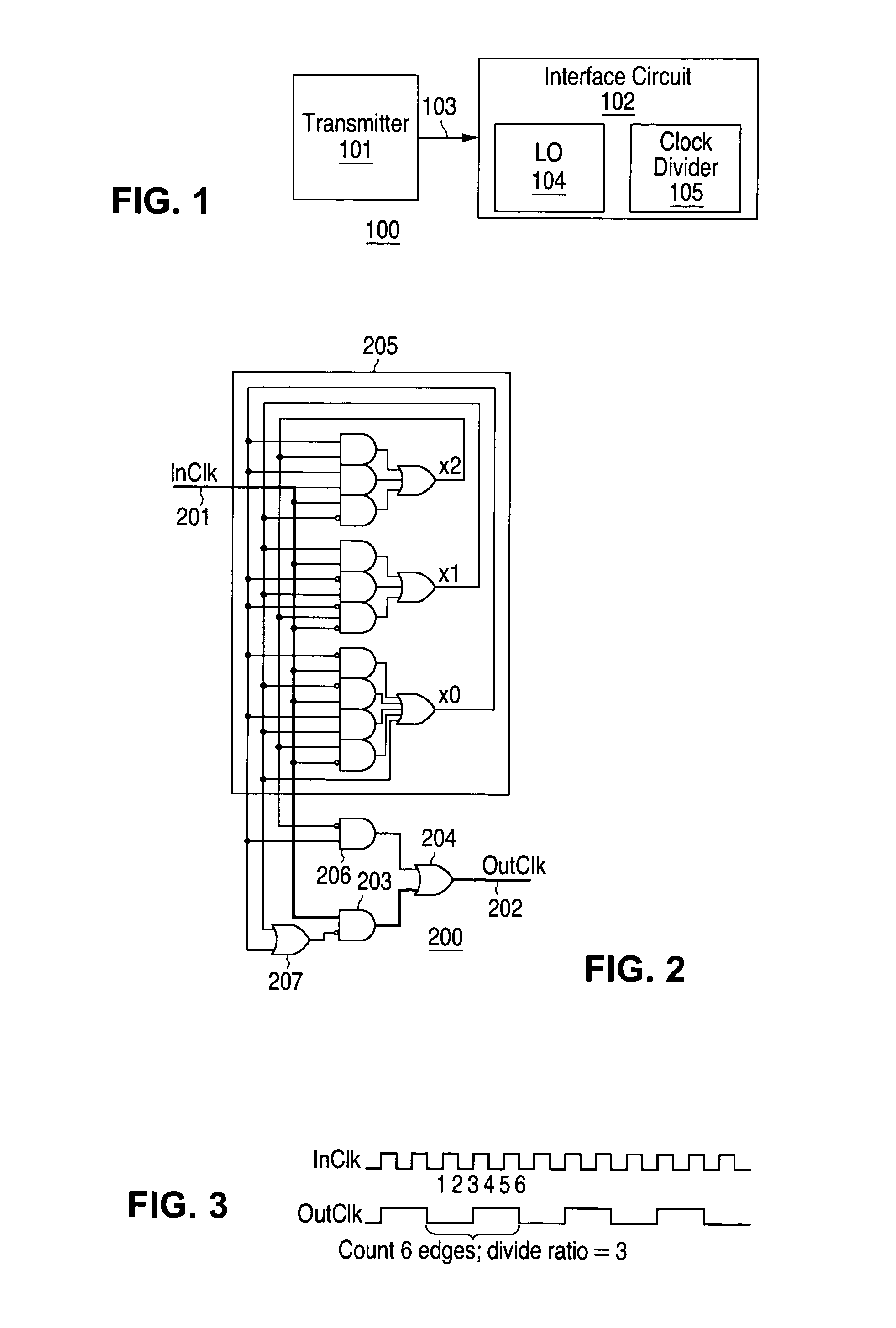
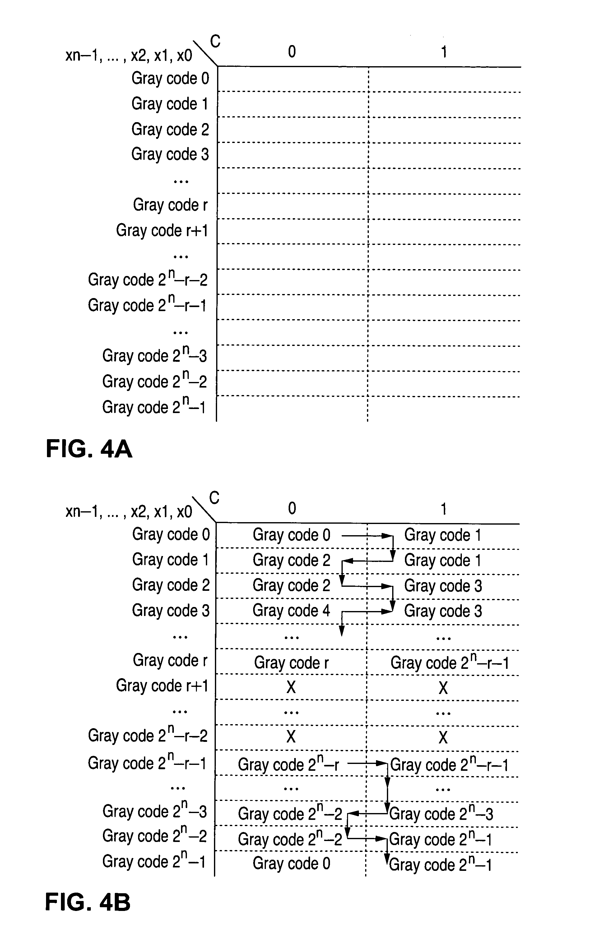
[0011]To address the above-discussed deficiencies of the prior art, it is a primary object of the present invention to provide, for use in a wireless receiver for a wireless communications system, an edge counter counting both rising and falling edges of an input signal, implemented with combinational logic only and without flip-flops. The combinational logic is designed using intermediate signals and state transitions producing an output signal having a cycle corresponding to a predetermined odd or even number of input signal edges, with the logic optimized and protected against entry into “stuck” states. A low power, low gate count edge counter is thus implemented with an output signal duty cycle at least as balanced as the input counter duty cycle.

[0012]The foregoing has outlined rather broadly the features and technical advantages of the present invention so that those skilled in the art may better understand the detailed description of the invention that follows. Additional fea...


PUM


Abstract

An edge counter counting both rising and falling edges of an input signal is implemented with combinational logic, without using flip-flops. The combinational logic is designed using intermediate signals and state transitions producing an output signal having a cycle corresponding to a predetermined odd or even number of input signal edges, with the logic optimized and protected against entry into “stuck” states. A low power, low gate count edge counter is thus implemented with an output signal duty cycle at least as balanced as the input counter duty cycle.

Description

TECHNICAL FIELD OF THE INVENTION[0001]The present invention is directed, in general, to edge counters and, more specifically, to implementing edge counters with minimum gate delay.BACKGROUND OF THE INVENTION[0002]Conventional counters typically only count one type of edge (rising or falling) of the input signal, and cannot achieve a 50 / 50 duty cycle output when the divide ratio is odd. Most conventional counter designs, an example of which is depicted in FIG. 6, use flip-flop cells together with combinational feedback logic and have a long latency delay, generally a three-gate delay minimum (where a D flip-flop is considered to incur a two-gate delay). In addition, multiple gate paths, usually resulting from a logical OR function combining two signal paths, result in asymmetrical responses on positive and negative events. Conventional designs also have a high AND / OR logic gate count, with the example in FIGURE X having 27 (six AND / OR gates in each of the four D flip-flop).[0003]Ther...

Claims


Application Information

Patent Timeline
Patent Type & Authority Patents(United States)
IPC IPC(8): H03K23/00
CPCH03K23/40H03K23/005
Inventor CHEUNG, HUNG K.WONG, HEE
Owner NAT SEMICON CORP
Why Eureka
Try Eureka