
Device and method for determining the focus position of a laser beam

a laser beam and focus position technology, applied in the field of laser beam focus position determination devices, can solve the problems of affecting the measurement accuracy, not knowing the precise focus position of laser pulses in the projection direction with a sufficiently high accuracy, and requiring a lot of metrological effort for accurate measurements

Active Publication Date: 2014-04-17
ZIEMER OPHTHALMIC SYST
View PDF11 Cites 14 Cited by
  • Summary
  • Abstract
  • Description
  • Claims
  • Application Information

AI Technical Summary

Benefits of technology

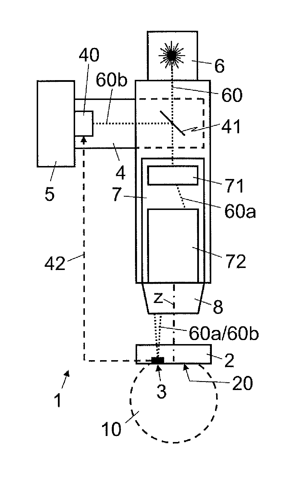
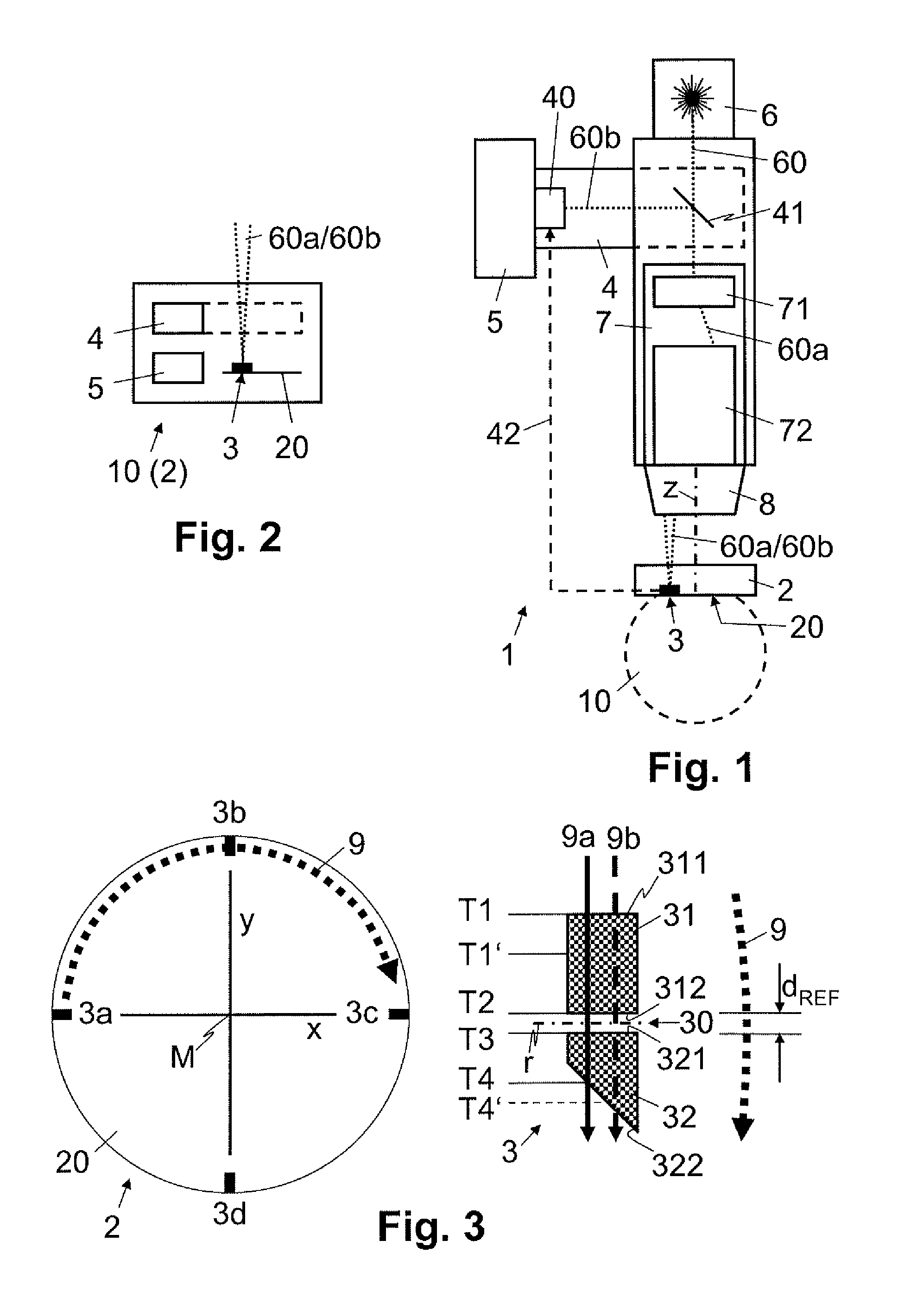
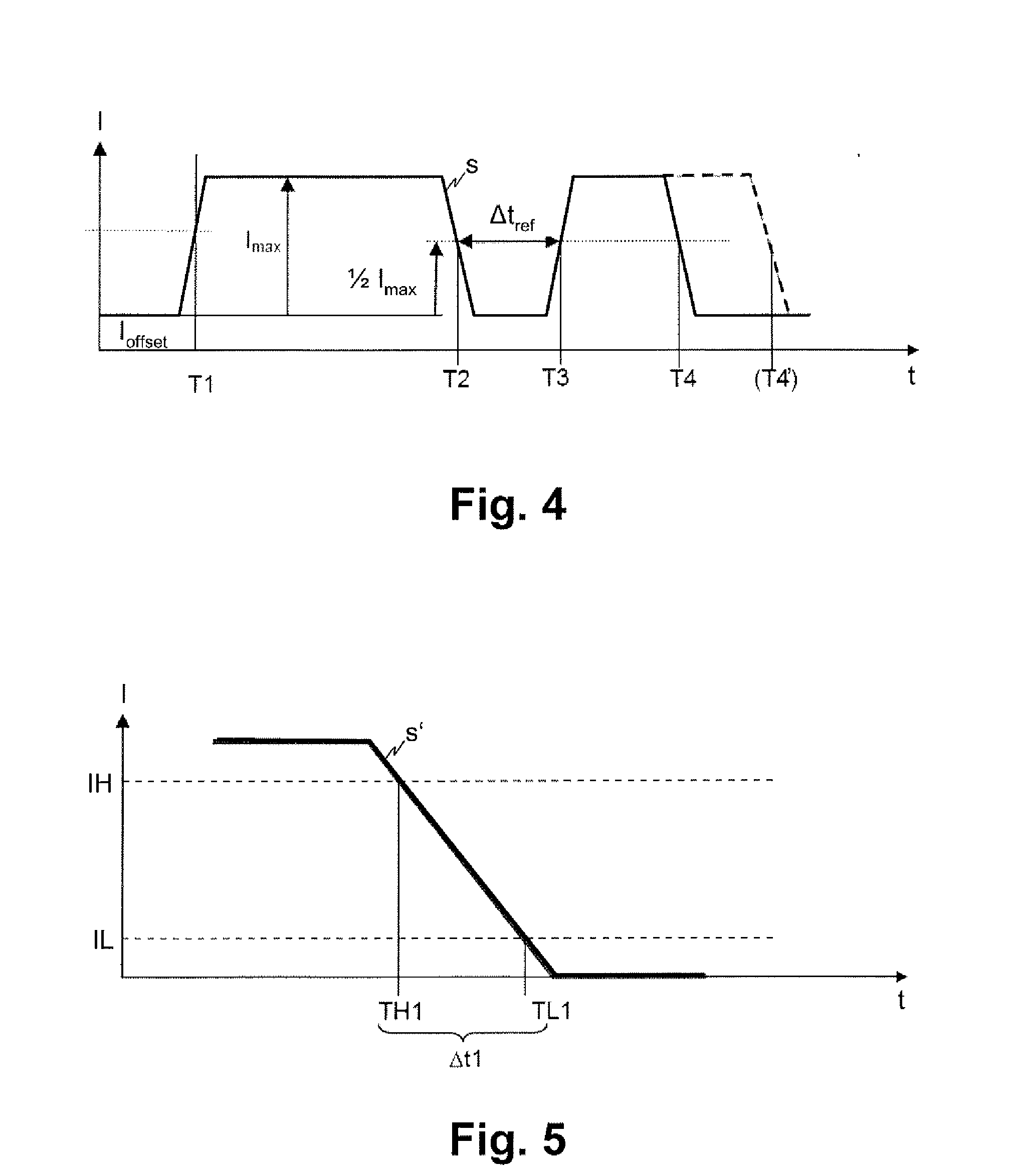
The present invention is about a system for determining the focus position of a laser beam in an ophthalmological laser projection system. It uses a measurement marking applied to a reference area, which is passed over by the laser beam along a scanning path. The measurement signal created by passing over the measurement marking is captured, and the time values of signal edges created when passing over the edges of the measurement marking are determined. The focus position is determined based on these time values. This system allows for precise focus positioning without the need for focusing movements during the measurement. Additionally, the measurement marking can be designed with a gap or bar having a known width, which makes it easier to determine the focus position even if the scanning speed is variable.

Problems solved by technology

As a result of production tolerances and / or thermal expansions during the production and operation of ophthalmological laser projection systems, the precise focus position of the laser pulses in the projection direction is generally not known with a sufficiently high accuracy with respect to the ophthalmological laser projection system, more particularly with respect to the projection lens and / or a contact body through which the laser pulses are projected into the tissue.
The method as per EP 2 069 099 requires a focusing movement for determining the surfaces, which can adversely affect the measurement accuracy.
Moreover, the confocal detection supplies very weak signals, and therefore much metrological effort is required for accurate measurements.

Method used


Image

  • Device and method for determining the focus position of a laser beam
  • Device and method for determining the focus position of a laser beam
  • Device and method for determining the focus position of a laser beam

Examples


Embodiment Construction

[0004]It is an object of the present invention to propose a device and a method for determining the focus position of a laser beam in an ophthalmological laser projection system, which, at the very least, do not have some of the disadvantages of known systems. In particular, it is an object of the present invention to propose a device and a method for determining the focus position in the projection direction of the laser beam, which make do without focusing movements during the measurement procedure.

[0005]According to the present invention, these objects are achieved by the features of the independent claims. Moreover, further advantageous embodiments emerge from the dependent claims and the description.

[0006]The aforementioned objects are more particularly achieved by the present invention by virtue of the fact that, in order to determine the focus position of a laser beam in an ophthalmological laser projection system, at least one measurement marking applied to a reference area,...


PUM

PropertyMeasurementUnit
Timeaaaaaaaaaa
Widthaaaaaaaaaa

Abstract

In order to determine the focus position of a laser beam (60, 60a) in an ophthalmological laser projection system (1), at least one measurement marking (3) applied to a reference area (20) is passed over by means of the laser beam (60, 60a) along a scanning path. A measurement signal created by passing over the measurement marking (3) is captured. Time values from at least one signal edge created in the measurement signal when passing over edges of the measurement marking (3) are determined and the focus position is established on the basis of the time values. By scanning defined measurement markings (3) and establishing time values of signal edges created when edges of the measurement marking (3) are passed over, it is possible to determine the focus position of the laser beam (60, 60a) without focusing movements being required for this during the measurement.

Description

TECHNICAL FIELD [0001]The present invention relates to a device and a method for determining the focus position of a laser beam in an ophthalmological laser projection system. The present invention more particularly relates to a device and a method for determining the focus position in the projection direction of the laser beam.PRIOR ART [0002]In ophthalmology, pulsed laser beams, for example laser pulses with a pulse duration in the femtosecond range (1 fs=10−15 s), are used for treating eye tissue. In the process, incisions are carried out by focused projection of the laser pulses into the eye tissue. As a result of production tolerances and / or thermal expansions during the production and operation of ophthalmological laser projection systems, the precise focus position of the laser pulses in the projection direction is generally not known with a sufficiently high accuracy with respect to the ophthalmological laser projection system, more particularly with respect to the projectio...

Claims


Application Information

Patent Timeline
IPC IPC(8): G01M11/02
CPCG01M11/02A61F9/00825A61F9/009A61F2009/00844A61F2009/0087A61F2009/00872A61F2009/00897B23K26/0006B23K26/0821B23K26/042B23K26/0624B23K2103/32A61N5/0613
Inventor RATHJEN, CHRISTIAN
Owner ZIEMER OPHTHALMIC SYST
Learn More