Contactless power transfer system

a power transfer system and contactless technology, applied in tomography, instruments, nuclear engineering, etc., can solve the problems of brush and slip ring mechanism, increase the weight, volume and complexity of the system, and certain disadvantages of the rotating gantry based scanner system

Active Publication Date: 2007-03-27
GENERAL ELECTRIC CO
View PDF8 Cites 199 Cited by
  • Summary
  • Abstract
  • Description
  • Claims
  • Application Information

AI Technical Summary

Benefits of technology

[0008]Optionally, a high-voltage component may be disposed on the rotating member, with the secondary side providing power at a high-voltage to the high-voltage component. In addition, a low-voltage component may be disposed on the rotating member, with the secondary side providing power at a low-voltage to the low-voltage component. Optionally, the rotating core may include an E-shaped cross-section divided into arcuate sections, such that each of th

Problems solved by technology

However, rotating gantry based scanner systems have experienced certain disadvantages.
The high-voltage tank and inverter on the rotating gantry portion increases the weight, volume and complexity of the system.
Furthermore, t

Method used


Image

  • Contactless power transfer system
  • Contactless power transfer system
  • Contactless power transfer system

Examples


Embodiment Construction

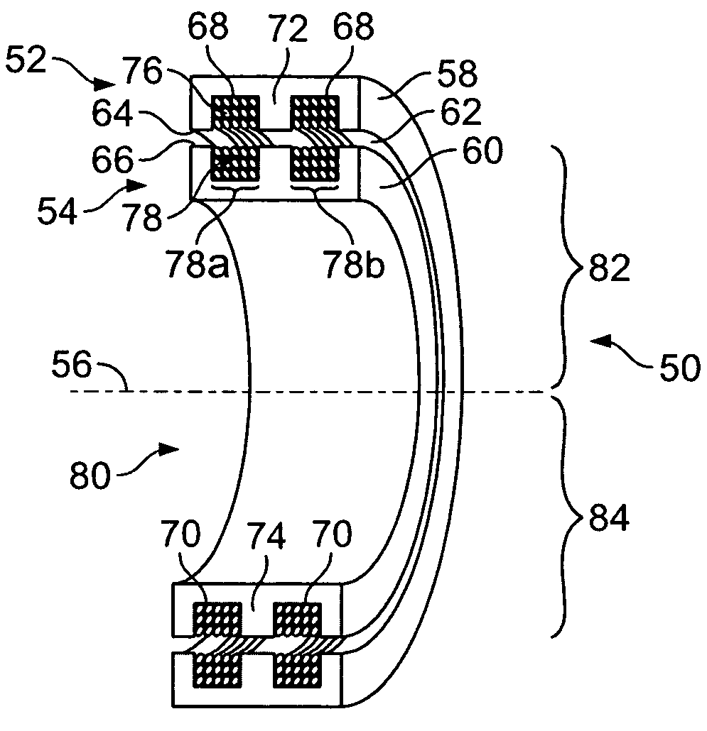
[0023]The terms “low-voltage” and “high-voltage” as used throughout are not intended to represent absolute valves, but instead are intended merely to indicate a relative relation to one another.

[0024]FIG. 1 illustrates a contactless power transfer system 50 formed in accordance with an embodiment of the present invention. The system 50 includes a stationary member 52 and a rotating member 54 located proximate one another and in a concentric arrangement about axis 56. The rotating member 54 rotates about axis 56 relative to the stationary member 52. By way of example, the stationary member 52 may simply represent a stator, while the rotating member 54 may represent a rotor, both of which may be coupled to a common framework, such as a gantry (e.g., see FIGS. 10 and 12). The stationary member 52 has a stationary core 58, while the rotating member 54 has a rotating core 60. The stationary and rotating cores 58 and 60 have corresponding inner and outer surfaces 64 and 66, respectively. ...


PUM


Abstract

In accordance with one embodiment, a contactless power transfer system is provided that comprises a stationary member including a power input configured to receive power at first voltage from a power supply. The system further includes a rotating member rotatably coupled to the stationary member and a rotary transformer. The rotary transformer has primary and secondary sides, with the primary side being disposed on the stationary member. The primary side has a primary winding that receives power at the first voltage from the power input. The secondary side is disposed on the rotating member and produces power at a second voltage. The secondary side has a rotating core and separate secondary sub-windings, each of which has forward and return paths that are circumferentially disposed about the rotating core. The forward and return paths of each of the sub-windings rotate proximate to, and are disposed a substantially equal distance from, the primary winding disposed on the stationary member.

Description

BACKGROUND OF THE INVENTION[0001]Embodiments of the present invention relate generally to power transfer mechanisms and, more particularly, to a contactless power transfer system.[0002]High-voltage power transformers are used in a variety of applications, such as in baggage scanner systems, computed tomography (CT) systems and the like. CT systems are often used to obtain non-invasive sectional images of test objects, particularly internal images of human tissue for medical analysis and treatment. Current baggage scanner systems and CT systems position the test object, such as luggage or a patient, on a conveyor belt or table within a central aperture of a rotating frame which is supported by a stationary frame. The rotating frame includes an x-ray source and a detector array positioned on opposite sides of the aperture, both of which rotate around the test object being imaged. At each of several angular positions along the rotational path (also referred to as “projections”), the x-...

Claims


Application Information

Patent Timeline
IPC IPC(8): H05G1/10H05G1/00H05G1/12
CPCA61B6/032H01F38/18A61B6/56
Inventor KATCHA, JASON STUARTSCHMIDT, JONATHAN RICHARD
Owner GENERAL ELECTRIC CO
Why Eureka
Try Eureka