Radio with a distortion compensation capability

Inactive Publication Date: 2007-03-27
FUJITSU LTD
View PDF7 Cites 57 Cited by
  • Summary
  • Abstract
  • Description
  • Claims
  • Application Information

AI Technical Summary

Benefits of technology

[0038]Accordingly, it is a general object of the present invention to provide a radio equipped with a distortion compensation capability to improve the power-added efficiency so th

Problems solved by technology

The leakage power into an adjacent channel is strictly regulated, because it constitutes noise in other channels and causes degradation of the communication quality of the other channels and produces a detrimental effect on the capacity of the communication, as shown in FIG. 2A.
However, the HPA has to be equipped with capability greater than is required in its practical use, which can lead to an increase in cost and size.
In other words, it has a disadvantage in terms of inc

Method used


Image

  • Radio with a distortion compensation capability
  • Radio with a distortion compensation capability
  • Radio with a distortion compensation capability

Examples


first embodiment

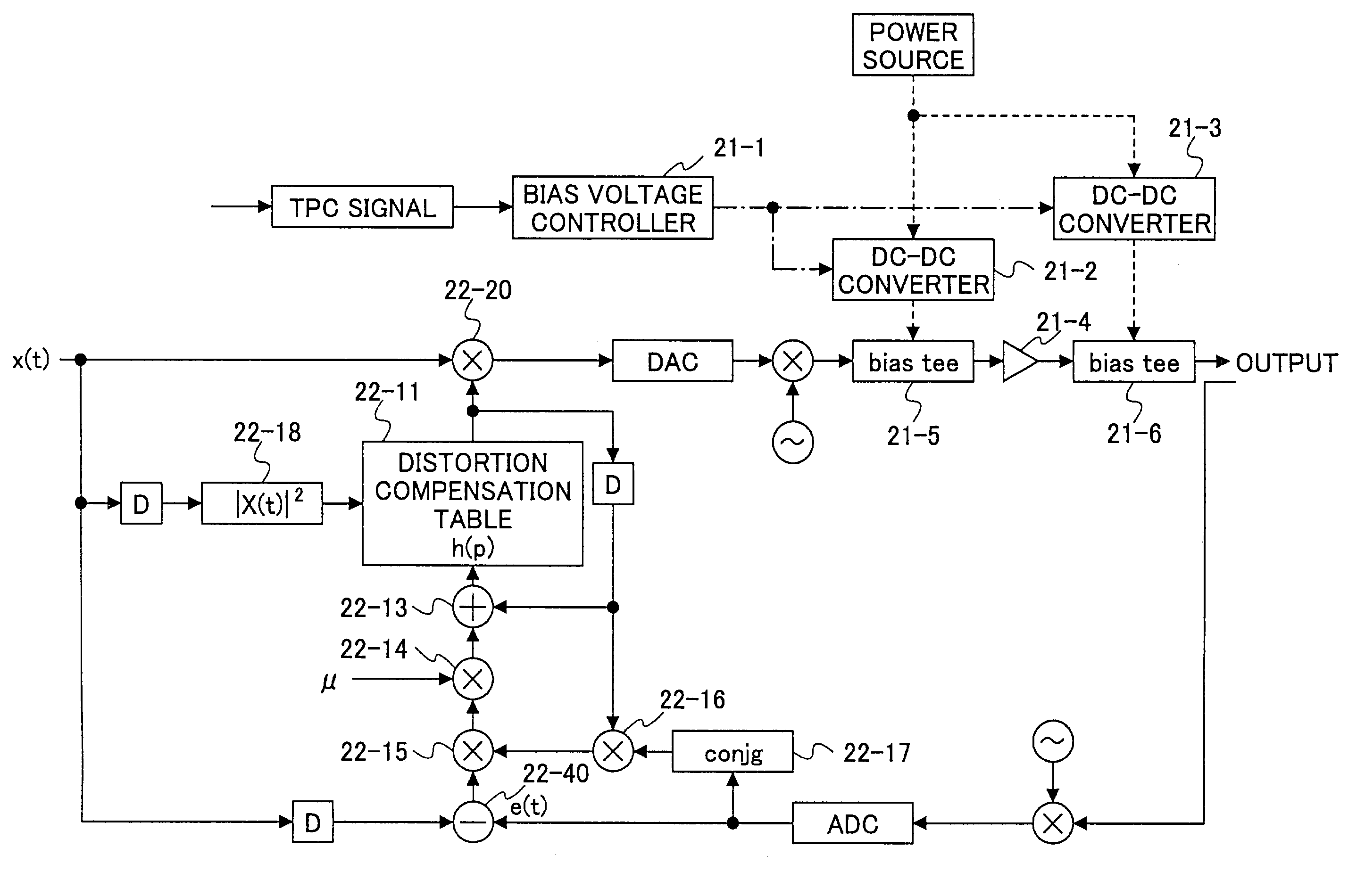
[0081]FIG. 7 shows the present invention. In this embodiment, transmit power (output power) is calculated at a bias voltage controller 21-1 based on a transmit power control (TPC) signal received from a base station. The most effective bias voltage is determined based on the calculated output power. In this embodiment, although the descriptions are directed to control of the bias voltage, it is also possible to control the power supply voltage supplied for the operation of the HPA.

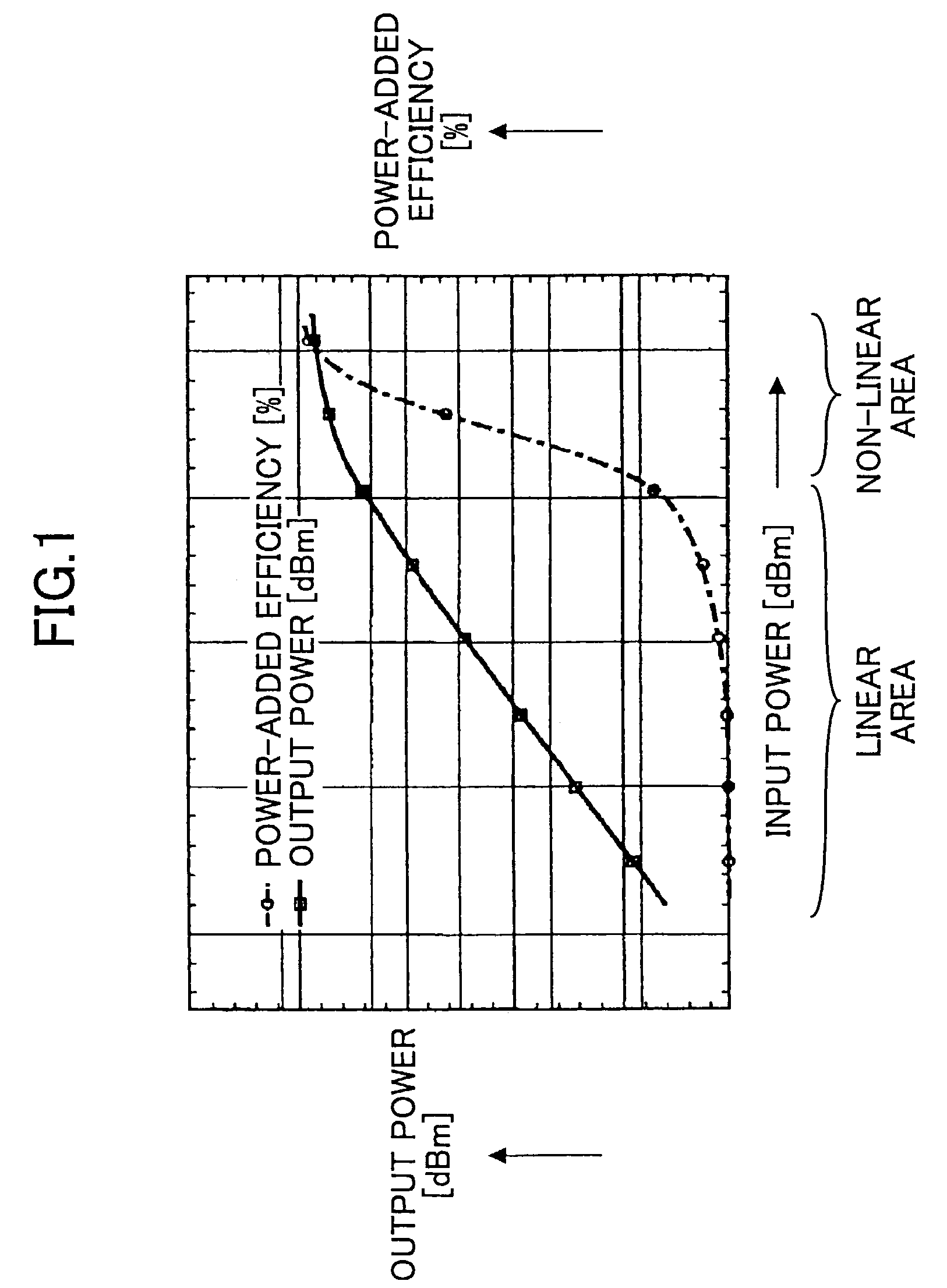
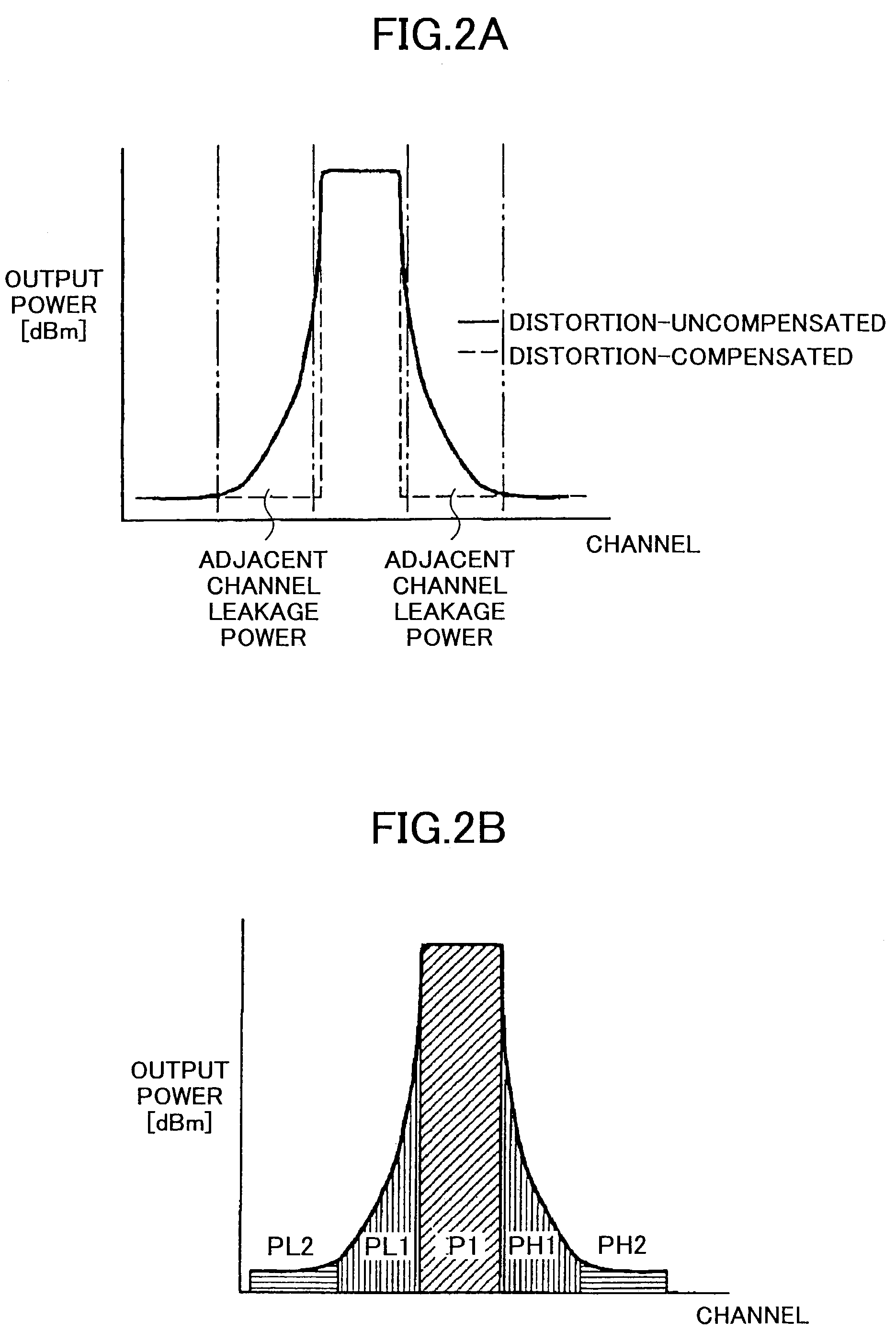
[0082]Referring to FIG. 4A for the description of this embodiment, the bias voltage, which maximizes the power-added efficiency versus the transmit power, is selected, as shown in FIG. 4A. However, since the selection of the bias voltage where the power-added efficiency becomes the maximum means the use of the non-linear area of the HPA, the level of distortion of the HPA is large. In other words, it causes the degradation of the Adjacent Channel Leakage power Ratio (ACLR). However, the Adjacent Channel Le...

fourth embodiment

[0093]Next, the present invention will be explained with reference to FIG. 11. Although the aforementioned distortion compensation table 22-11 of the linearizer is defined in one dimension in the preceding embodiments, the distortion compensation table 5-1 is defined in two dimensions in this embodiment. In other words, bias voltage is added to the aforementioned distortion compensation table 22-11 as an additional parameter. Specifically, in this embodiment, the two-dimensional table 5-1 stores and retains the distortion compensation coefficients with respect to two parameters, that is to say, the transmit power and the bias voltage. For that reason, it becomes possible to use the distortion compensation coefficient according to the bias voltage of the HPA, whereby accelerating the convergence time taken for the distortion compensation as compared with the cases in the preceding embodiments.

fifth embodiment

[0094]Next, the present invention will be explained with reference to FIG. 12. By the way, if a steep change in the bias voltage occurs during the bias voltage control according to the preceding embodiments, it causes the spectrum of the output signal of the HPA to spread, resulting in an increase of noise, that is to say, an increase of the distortion level.

[0095]In order to suppress the steep change, with the same configuration as in the fourth embodiment shown in FIG. 11, the low-pass filters (LPF) 6-1, 6-2 are provided at the output side of the DC—DC converters 21-2, 21-3, respectively, to cut the high-frequency components, as shown in FIG. 12A. In this way, the change of the bias voltage is smoothed, as shown in FIG. 12B, whereby reducing the distortion level due to the steep change of the bias voltage. Consequently, it becomes possible to avoid the spectrum of the output signal of the HPA from spreading.


PUM


Abstract

A radio comprises a power amplifier for amplifying a signal to be transmitted; a distortion compensation table storing distortion compensation coefficients for compensating a distortion of the power amplifier; a computing unit for updating the distortion compensation coefficient based on a difference between a transmission input signal and a transmission output signal; a bias voltage controller for applying a bias voltage to the power amplifier, said bias voltage determined based on a transmit control signal so as to maximize a power efficiency of the power amplifier.

Description

BACKGROUND OF THE INVENTION[0001]1. Field of the Invention[0002]The present invention relates to a radio for a W-CDMA (Wideband Code Division Multiple Access) mobile communication system and the like, which has a distortion compensation capability to reduce Adjacent Channel Leakage power by compensating a distortion of a transmission signal and to achieve high power-added efficiency of a power amplifier.[0003]2. Description of the Related Art[0004]I. Distortion and Efficiency of the High Power Amplifier.[0005]In wireless communication systems, especially in mobile communication systems such as W-CDMA and PDC, the transmit power is high and ranges from 10 mW to several tens of Watts. Since the transmit power has to be controlled according to the distance between one communication device and the other, the dynamic range of the transmit power becomes significantly wide. Thus, it is necessary to make use of a high power amplifier (HPA) that can avoid distorting a signal even at maximum ...

Claims


Application Information

Patent Timeline
IPC IPC(8): H04B1/04H03F1/32
CPCH03F1/3258H04B1/0475Y02B60/50H03F2201/3233
Inventor ODE, TAKAYOSHIMANIWA, TORU
Owner FUJITSU LTD
Why Eureka
Try Eureka