

High- frequency power amplifier
A power amplifier and frequency technology, applied in the direction of high-frequency amplifiers, power amplifiers, amplifiers, etc., can solve the problems of insufficient power-added efficiency improvement and power-added efficiency reduction, and achieve the effect of reducing distortion and reducing power consumption
- Summary
- Abstract
- Description
- Claims
- Application Information
AI Technical Summary
Problems solved by technology
Method used
Image


Examples
no. 1 approach
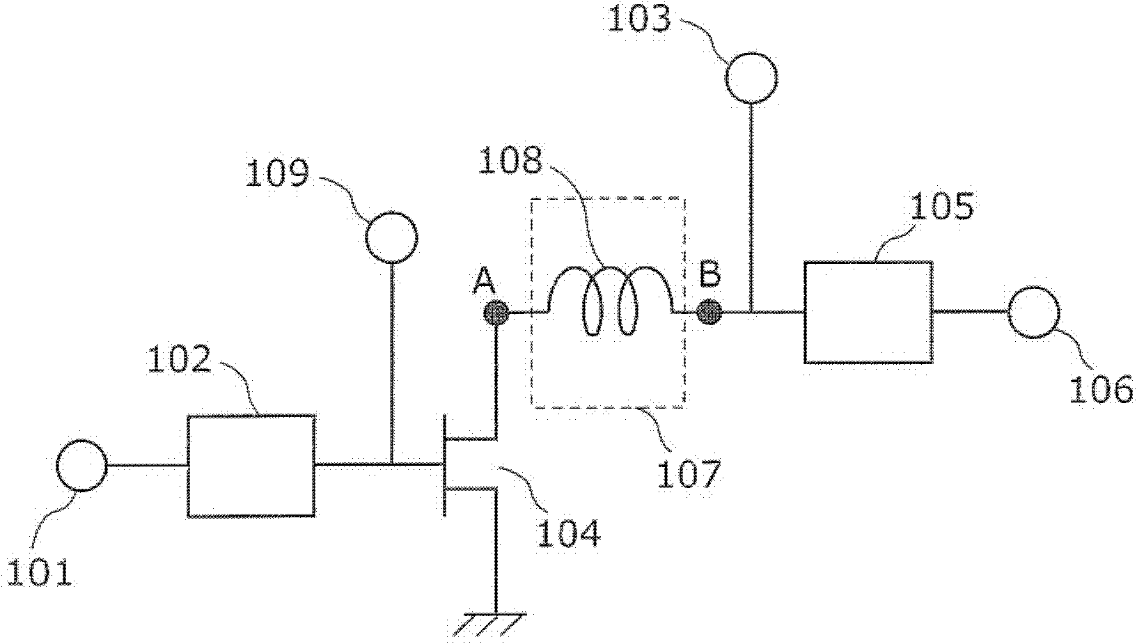
[0060] figure 1 A circuit diagram showing a high-frequency power amplifier according to the first embodiment of the present invention.
[0061] Such as figure 1 As shown, the high-frequency power amplifier according to the first embodiment of the present invention has: an input matching circuit 102 ; a transistor 104 which is an amplifying element; a reactance control circuit 107 ; and an output matching circuit 105 . Also, an input terminal 101 for a high-frequency signal is connected to an input side of the input matching circuit 102 , and a bias terminal 109 is connected to an output side of the input matching circuit 102 . A DC voltage for driving the transistor 104 is applied to the gate of the transistor 104 via a bias terminal 109 . In addition, a bias terminal 103 is connected to the input side of the output matching circuit 105 . A DC voltage for driving the transistor 104 is applied to the drain of the transistor 104 via the bias terminal 103 . Furthermore, an ...
no. 2 approach
[0100] Below, use Figure 10 A high-frequency power amplifier according to a second embodiment of the present invention will be described. Figure 10 It is a circuit diagram of a high-frequency power amplifier according to a second embodiment of the present invention.
[0101] The difference between the high-frequency amplifier of the second embodiment of the present invention and the high-frequency amplifier of the first embodiment is the configuration of the reactance control circuit 107 . That is, in this embodiment, the microstrip line 401 is used as the reactance control circuit 107 . In addition, other circuit structures are the same as those of the first embodiment, so that in Figure 10 neutralize figure 1 The same reference numerals are used for the same structural elements, and descriptions thereof are omitted.
[0102] In this embodiment, the reactance component of the microstrip line 401 constituting the reactance control circuit 107 can be adjusted by its lin...
no. 3 approach
[0104] Below, use Figure 11 A high-frequency power amplifier according to a third embodiment of the present invention will be described. Figure 11 It is a circuit diagram of a high-frequency power amplifier according to a third embodiment of the present invention.
[0105] The difference between the high-frequency amplifier of the third embodiment of the present invention and the high-frequency amplifier of the first embodiment is the configuration of the reactance control circuit 107 . That is, in the present embodiment, a series resonance circuit of an inductor 501 and a capacitor 502 is used as the reactance control circuit 107 . In addition, other circuit structures are the same as those of the first embodiment, so that in Figure 11 neutralize figure 1 The same reference numerals are used for the same structural elements, and descriptions thereof are omitted.
[0106] Here, when the resonant frequency is F, the parasitic capacitance of the transistor 104 is C, the ...
PUM
 Abstract
Description
Claims
Application Information