Light bulb installation and removal device

a technology for installing and removing devices and light bulbs, which is applied in the manufacture of electrode systems, electric discharge tubes/lamps, liquid handling, etc., can solve the problems of limited access to light bulbs and individual difficulty, and achieve the effect of improving household and workplace safety

Inactive Publication Date: 2007-04-03
WILLIAMS STEVEN ANDREW
View PDF21 Cites 21 Cited by
  • Summary
  • Abstract
  • Description
  • Claims
  • Application Information

AI Technical Summary

Benefits of technology

[0006]The device of the invention improves household and workplace safety by eliminating the need for an individual to climb a ladder to remove and install a light bulb in a ceiling, roof eve, and the like. The device can be used with a handle, e.g., telescoping, to reach light bulbs in high locations.

Problems solved by technology

The device can be particularly useful in reaching bulbs in recessed can lighting fixtures, which offers limited accessibility to the light bulb.
Certain designs of recessed can lighting may cause an individual difficulty when trying to grip the light bulb with their fingers, since the space between the light bulb and the recessed can is typically only about 0.64 cm (0.25 inches) or less.

Method used


Image

  • Light bulb installation and removal device
  • Light bulb installation and removal device
  • Light bulb installation and removal device

Examples


Embodiment Construction

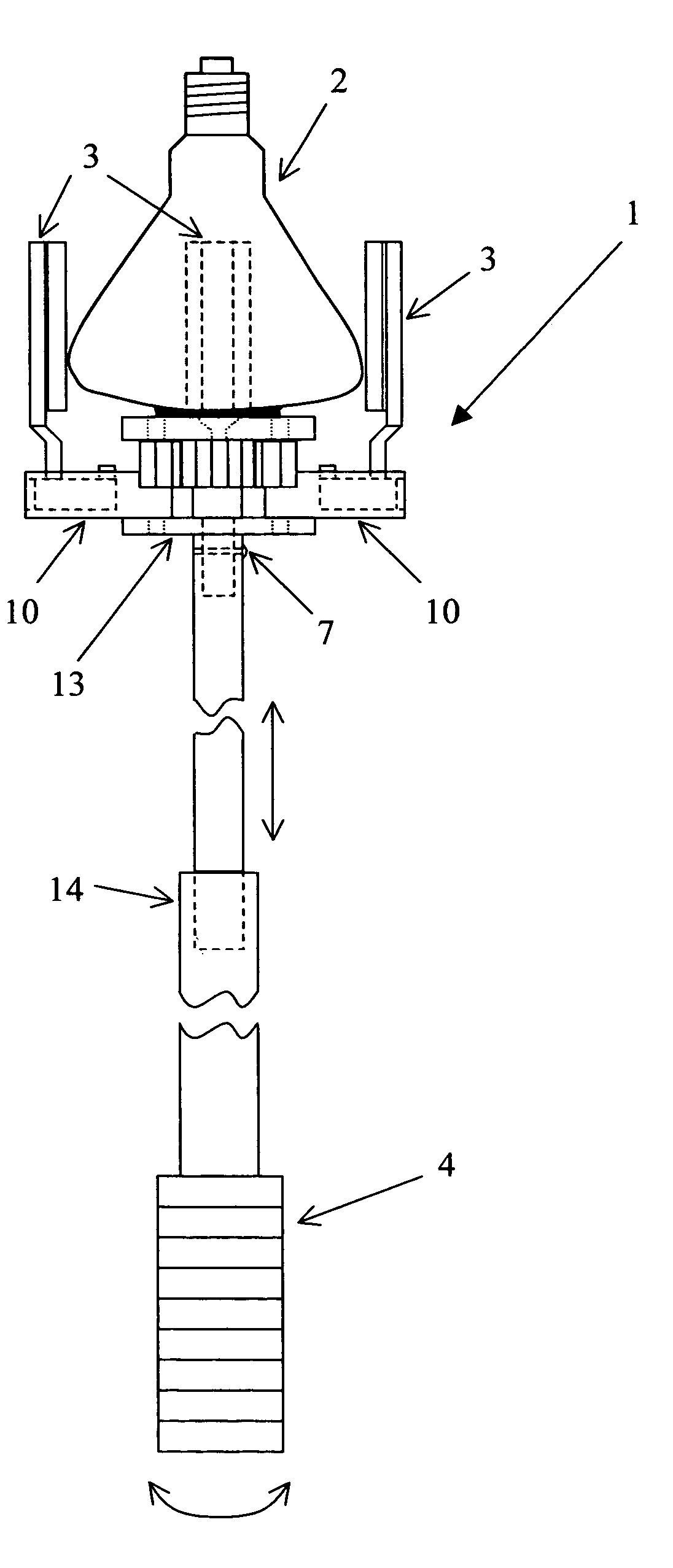
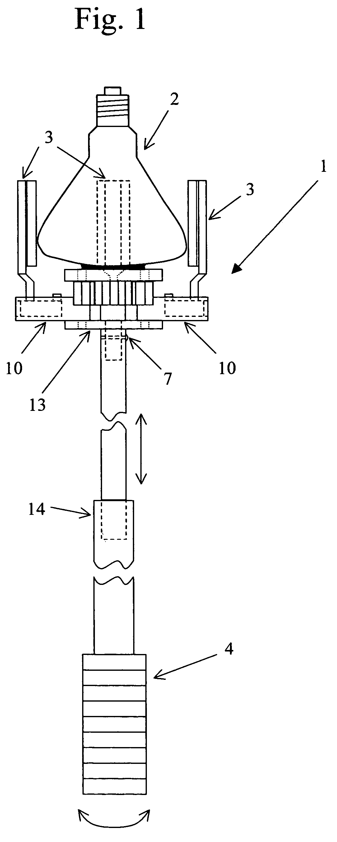
[0014]FIG. 1 shows the object gripping device 1 gripping a light bulb 2, e.g. found in standard recessed lighting fixture (not shown). Three vertical gripping posts 3 are shown equally gripping the bulb 2. The three vertical gripping posts 3 can preferably each be spaced every 120 degrees around the bulb's circumference. The gripping device 1 is held and operated by the user with the telescoping handle 4. The handle 4 extends or retracts from point 14. To tighten or loosen a bulb 2 from its fixture, the handle 4 is rotated in the direction desired by the user, either clockwise or counter-clockwise. While a telescoping handle is shown, the handle need not include the telescoping feature.

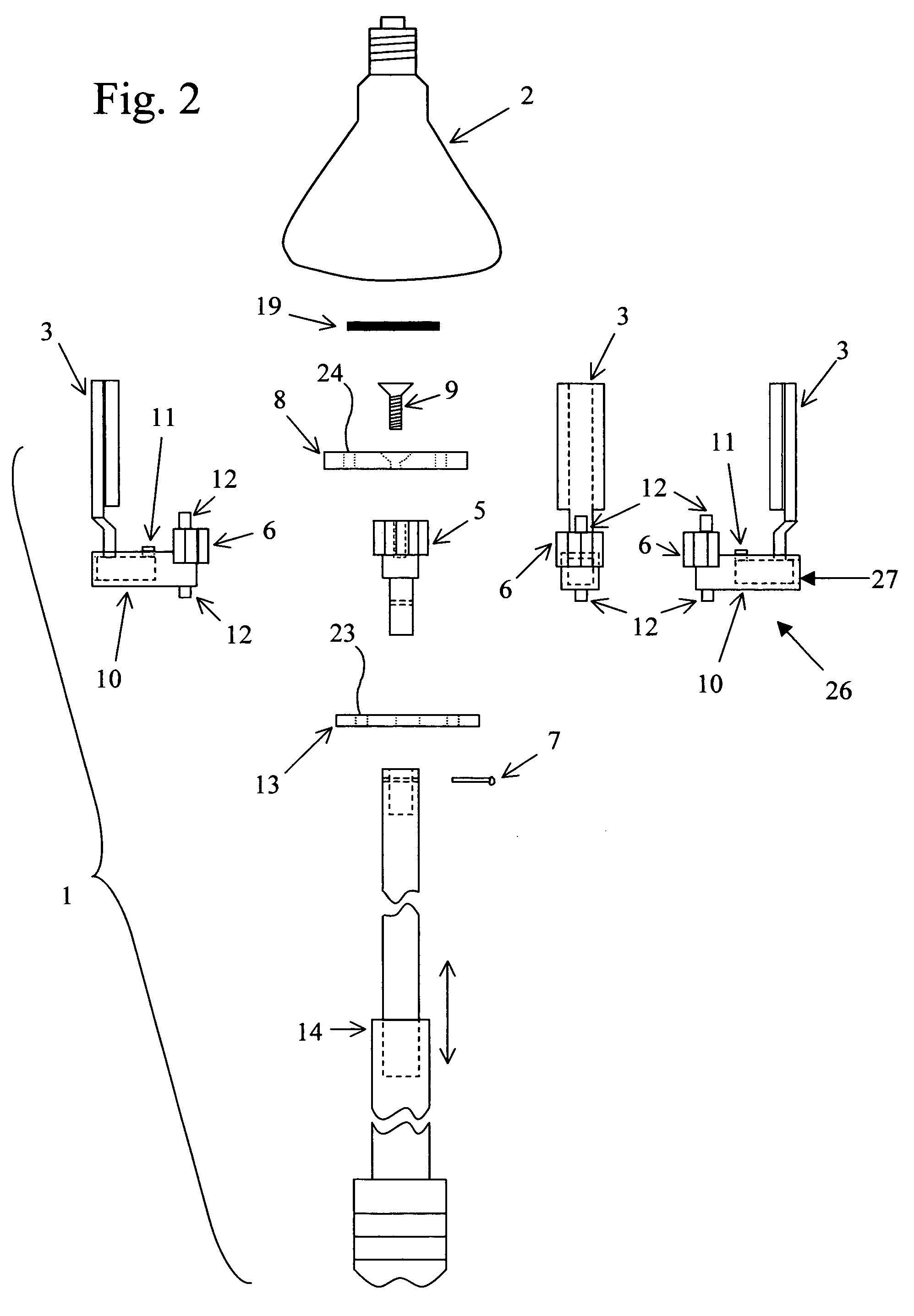
[0015]FIG. 2 is an exploded view of the gripping device 1. As can be seen, there are relatively few components in the object gripping device 1. The gear that is driven by the user and affixed to the handle 4 is a sun gear 5, and is in the center of the object gripping device 1. The sun gear 5 is attac...


PUM


Abstract

An object gripping device for removing and installing bulbs and other objects. The device has around its circumference three or more vertical gripping posts. The device uses a sun gear and planetary gears to transmit the user's twisting motion to a gripping force applied equally around the object's circumference. Furthermore, the gearing ratio can be adjusted to create more or less leverage or gripping force applied to the bulb or object. The device could also be applied to gripping any object that is semi-cylindrical in shape. For instance, a robot can use the invented gear system to pick up or grip objects in a factory, laboratory, hospital, space exploration or home setting. Instead of a handle used to rotate the sun gear a drive shaft can be attached. An electric motor, a gas or diesel engine, a hydraulic power pack can rotate the drive shaft.

Description

CROSS REFERENCE TO RELATED APPLICATIONS[0001]This application is based on and claims priority to Provisional Patent Application No. 60 / 518,992, entitled “Object Gripping Device”, filed on Nov. 12, 2003.BACKGROUND[0002]The invention relates to the field of devices for gripping objects with a circular circumference and even curved vertical surfaces, such as light bulbs. More specifically, the invention relates to a device for gripping and turning for the installation and removal of objects such as light bulbs, and is particularly suitable for installing and removing light bulbs in high and / or poorly accessible environments, such as recessed can lighting fixtures.[0003]One purpose of the invention is to provide a device to grip a light bulb or any round object securely around its circumference while it is being removed, moved and installed by the user. The device of the invention can be mounted on the end of a rod, e.g., telescoping, allowing the user to access light bulbs in ceilings,...

Claims


Application Information

Patent Timeline
Patent Type & Authority Patents(United States)
IPC IPC(8): H01K3/32B25B13/28B25J15/10H01J9/00
CPCB25J15/10H01J9/003H01K3/32
Inventor WILLIAMS, STEVEN ANDREW
Owner WILLIAMS STEVEN ANDREW
Why Eureka
Try Eureka