
Refining element

a technology of refiners and elements, applied in the field of refiners, can solve the problems of limiting the possible energy input, affecting the capacity and operation stability of the refiner, and affecting the development of steam, so as to achieve the effect of staying in the refining gap

Active Publication Date: 2007-04-03
VALMET TECH INC
View PDF9 Cites 2 Cited by
  • Summary
  • Abstract
  • Description
  • Claims
  • Application Information

AI Technical Summary

Benefits of technology

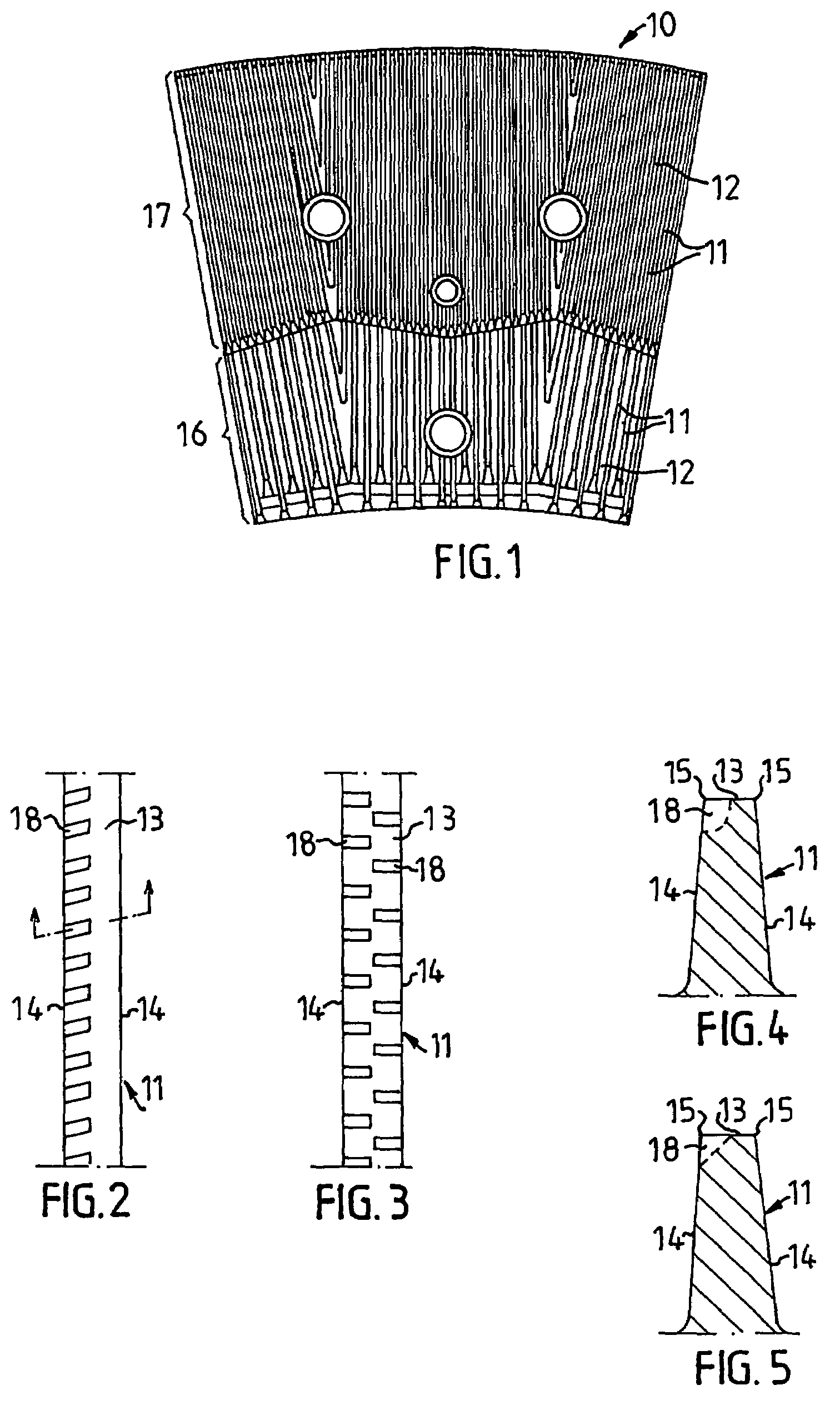
[0014]The present invention offers a solution to the above problems. According to the present invention, the bars are provided with a plurality of recesses, which are arranged in the longitudinal edges of the bars. The recesses are directed across the bars or so as to form an angle of at least 45° with the bars. The recesses are open both to the upper surface of the bars and to one side surface or to both side surfaces. By this configuration of the bars the flow of the fibrous material through the refining gap will be braked, so that the stay-time of the fibers in the refining gap will be longer and the working thereby will be increased, without braking the steam or liquid flow in the grooves between the bars so that the flow of the fibrous material is disturbed.

Problems solved by technology

These dams, however, form an obstacle for the steam developing in the refining gap during the refining.
This high steam pressure has a negative effect on the capacity and operational stability of the refiner.
It also implies a limitation on the possible energy input.
The developed steam, thus, will be forced by the flow restrictions upwardly out of the grooves, and will disturb the material flow through the refining gap.
This, however, results in reducing the material concentration to a low level, and thus in a deteriorated pulp quality.
It can imply, however, that the flow through the refining gap will be much too low.

Method used


Image

  • Refining element
  • Refining element

Examples


Embodiment Construction

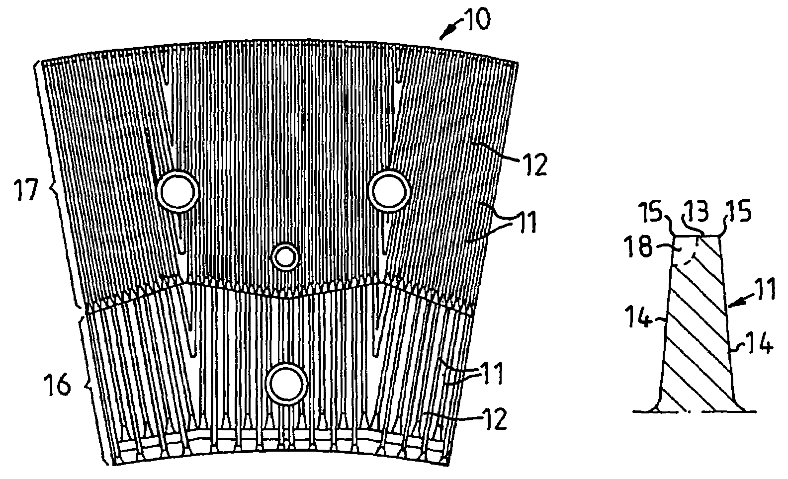
[0023]FIG. 1 shows a refining element 10 intended for refining fibrous material having a high concentration. The refining element 10 is provided with a pattern of bars 11 and intermediate grooves 12, in which the bars have upper surfaces 13 and side surfaces 14 with edges 15. The pattern is divided into two zones, an inner zone 16 and an outer zone 17, where the bars and grooves in the inner zone are coarser than in the outer zone. The bars in the inner zone are intended to bring about a first disintegration of the material and to advance the material outwardly to the outer zone. The bars in the outer zone are more tightly arranged, which yields more bar edges for effecting the substantial working and refining of the fibrous material. The pattern can also comprise more zones, where the pattern is usually made tighter from zone to zone, as seen radially outwardly.

[0024]FIG. 2 shows one embodiment of a bar 11 on a refining element according to the present invention. Along the bar 11 a...


PUM

PropertyMeasurementUnit
widthaaaaaaaaaa
widthaaaaaaaaaa
depthaaaaaaaaaa

Abstract

Refining elements for use with disc refiners for the processing of fibrous materials are disclosed. The refining element include a refining surface having a plurality of bars and intermediate grooves, with the bars having an upper surface and a pair of side surfaces defining longitudinal edges, with the plurality of bars including a plurality of recesses disposed along at least one of the longitudinal edges, the recesses including open portions in both the upper surface and one of the side surfaces thereof.

Description

CROSS-REFERENCE TO RELATED APPLICATIONS[0001]The present application is a national phase entry under 35 U.S.C. § 371 of International Application No. PCT / SE04 / 000678 filed May 5, 2004, published in English, which claims priority from Swedish Patent Application No. 0301525-2 filed May 23, 2003, all of which are incorporated herein by reference.FIELD OF THE INVENTION[0002]The present invention relates to refiners of the disc-type, with opposed refining discs rotating relative to one another. The refining discs are provided with refining elements, which between themselves form a refining gap with a refining zone for working fibrous material. The fibrous material preferably is lignocellulosic fibrous material and the refiner is used for the manufacture of, for example, reject pulp, recycled fiber pulp and mechanical pulps, such as board pulp, thermomechanical pulp (TMP) and chemi-thermo-mechanical pulp (CTMP) and for low-concentration refining chemical pulps.[0003]The present invention,...

Claims


Application Information

Patent Timeline
Patent Type & Authority Patents(United States)
IPC IPC(8): B02C7/12D21D1/30
CPCB02C7/12D21D1/306
Inventor VIRVING, NILS
Owner VALMET TECH INC
Learn More