Scalable imaging spectrometer

a spectrometer and imaging technology, applied in the field of imaging spectrometers, can solve the problems of limiting the performance of the spectrometer, increasing image blur, and one-dimensional arrays generally not being able to capture spatial information

Active Publication Date: 2007-04-03
RESONON
View PDF10 Cites 44 Cited by
  • Summary
  • Abstract
  • Description
  • Claims
  • Application Information

AI Technical Summary

Problems solved by technology

These spectrometers that use one-dimensional arrays generally cannot capture any spatial information about the particular light beam and therefore generate only spectral information.
As the field of view increases, however, off-axis aberrations, both in the focusing optic and in the downstream spectral dispersive module of the system, generate increasingly large image blur and limit the performance of the spectrometer.
Such scaling poses a variety of problems in performance.
In general, such a reduction in throughput unacceptably reduces the signal-to-noise ratio of the detectors.
Although one might be tempted to therefore reduce the field of view to compensate for the increase in NA, in order to reduce the off-axis aberrations in the system, in general this is unacceptable, as it is a compromise in performance.
In other words, the problem encountered with scaling down a spectrometer design is as follows.

Method used


Image

  • Scalable imaging spectrometer
  • Scalable imaging spectrometer
  • Scalable imaging spectrometer

Examples


Embodiment Construction

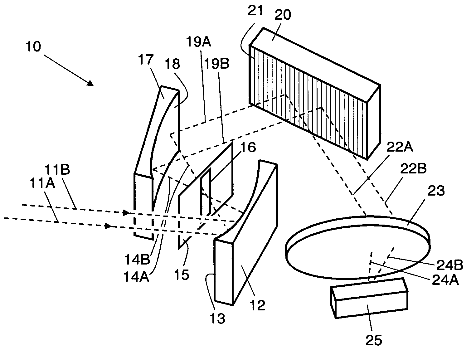
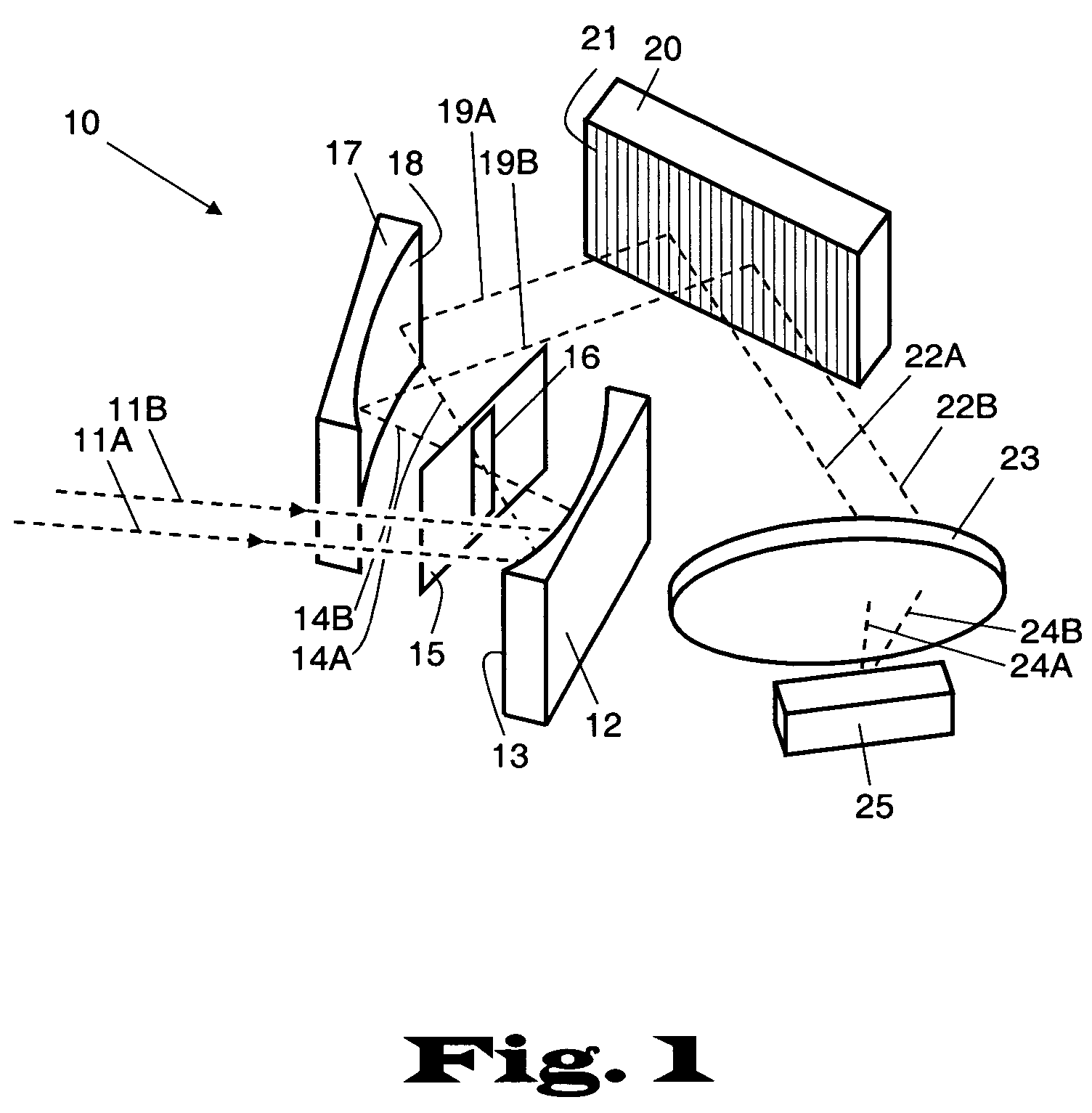
[0038]FIG. 1 is a perspective drawing of a scalable imaging spectrometer 10 that uses anamorphic optical elements and has reduced off-axis aberrations.

[0039]The imaging spectrometer 10 is commonly used for detection and analysis of relatively distant objects. For instance, the imaging spectrometer is commonly housed in an aircraft or UAV and may be flown over an object to be analyzed, which may be referred to as an object under test. The object under test is generally tested using ambient solar illumination, although thermal radiation or a specifically designed illumination system may also be used. Because the distance to the object under test is generally relatively large, say, greater than 100 meters, the rays arriving at the spectrometer from the object may be considered effectively collimated. In other words, rays originating from a common point on the distant object are essentially parallel when they reach the spectrometer.

[0040]The imaging spectrometer 10 may also be used for ...


PUM


Abstract

A scalable imaging spectrometer, using anamorphic optical elements to form an intermediate focus in only one dimension. Light reflects off an object to form an incident beam. The beam reflects off an anamorphic objective mirror to form a line focus at a slit. At the slit, the beam is focused along the spectral dimension, but remains substantially collimated along the spatial dimension. The beam is then recollimated in the spectral dimension by a second anamorphic mirror, reflects off a diffraction grating, passes through a lens, and is brought to focus on a two dimensional detector, which produces both spectral and spatial information about the object. Because there is no intermediate focus in the spatial dimension, there are no off-axis aberrations from the anamorphic mirrors, and the field of view may be substantially increased over prior art spectrometers in the spatial dimension.

Description

CROSS-REFERENCES TO RELATED APPLICATIONS[0001]This application claims the benefit of U.S. Provisional Application No. 60 / 620,433, filed Oct. 20, 2004 (Kehoe et al., “Scalable imaging spectrometer”), which hereby is incorporated herein in its entirety by reference thereto. This patent is also a continuation-in-part of and claims the benefit of U.S. patent application Ser. No. 10 / 998,110 filed Nov. 26, 2004 now abandoned (Kehoe et al., “Scalable imaging spectrometer”), which hereby is incorporated herein in its entirety by reference thereto.GOVERNMENT LICENSE RIGHTS[0002]The U.S. Government has a paid-up license in this invention and the right in limited circumstances to require the patent owner to license others on reasonable terms as provided for by the terms of Contract No. FA8650-04-M-1652 awarded by the United States Air Force.BACKGROUND OF THE INVENTION[0003]1. Field of the Invention[0004]The present invention is directed to imaging spectrometers, and more particularly to scalab...

Claims


Application Information

Patent Timeline
Patent Type & Authority Patents(United States)
IPC IPC(8): G01J3/28
CPCG01J3/02G01J3/0208G01J3/04G01J3/2823
Inventor KEHOE, MICHAEL R.SMITH, CASEY W.SWANSON, RAND C.
Owner RESONON
Why Eureka
Try Eureka