X-ray composite apparatus

a composite apparatus and x-ray technology, applied in the direction of material analysis using wave/particle radiation, instruments, nuclear engineering, etc., can solve the problem that the apparatus cannot perform element analysis by fluorescent x-rays, and achieve the effect of saving space and saving user's effor

Inactive Publication Date: 2013-09-26
RIGAKU CORP
View PDF3 Cites 30 Cited by
  • Summary
  • Abstract
  • Description
  • Claims
  • Application Information

AI Technical Summary

Benefits of technology

[0013]The present invention has been made in view of these circumstances and has an object to provide an X-ray composite apparatus capable of performing X-ray CT and element analysis by fluorescent X-rays efficiently with one unit of the apparatus.

Problems solved by technology

However, the objects of these apparatuses are X-ray CT and are not to perform each of the X-ray CT and the structural analysis by X-ray diffraction.
In addition, Patent Document 3 describes the apparatus capable of performing each of the X-ray CT and the structural analysis by the X-ray diffraction, but the apparatus cannot perform element analysis by fluorescent X-rays.

Method used


Image

  • X-ray composite apparatus
  • X-ray composite apparatus
  • X-ray composite apparatus

Examples


first embodiment

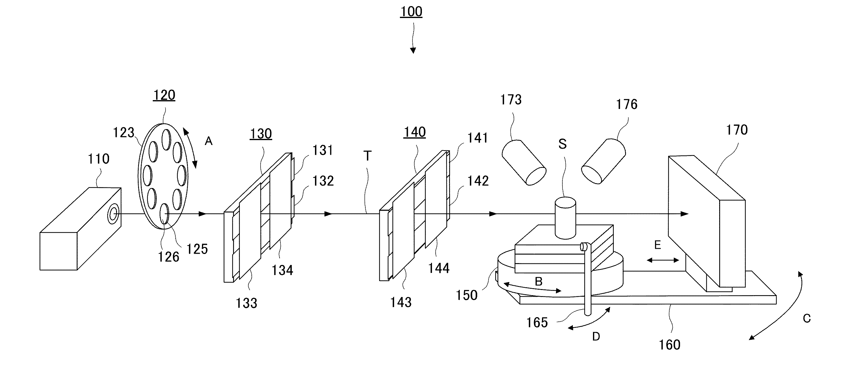
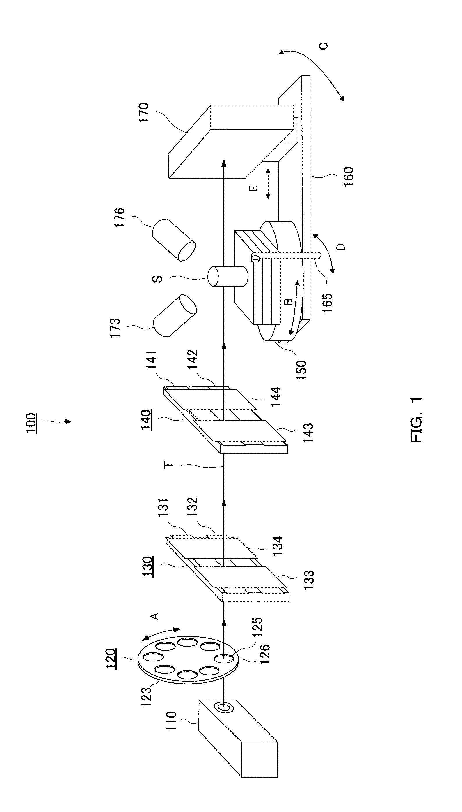
[0040]FIG. 1 is a perspective view illustrating an example of a configuration of an X-ray composite apparatus 100. As illustrated in FIG. 1, the X-ray composite apparatus 100 is composed of X-ray source 110, a revolver-type filter switching part 120, electric slits 130 and 140, a sample support 150, a 2θ mechanism 160, a beam stopper 165, a two-dimensional detector 170, a camera 173, and a fluorescent X-ray detector 176. In FIG. 1, an irradiation direction of an irradiation path T of X-rays is indicated by an arrow.

[0041]The X-ray source 110 generates X-rays by means of application of a predetermined tube voltage. As a target, molybdenum, tungsten, silver, copper or the like is used, for example. The voltage to be applied can be adjusted by user's operation. An applied voltage of approximately 150 kV is suitable in the case of performing X-ray CT and an applied voltage of approximately 100 kV is suitable in the case of performing X-ray diffraction analysis.

[0042]The revolver-type fi...

second embodiment

[0058]In the above-described embodiment, the electric slits 130 and 140 are used as a collimator part which switches between the cone beam and the parallel X-rays, but a collimator 230 capable of advancing / retreating on the X-ray irradiation path may be also used. FIG. 5 is a perspective view illustrating an X-ray composite apparatus 200 using the collimator 230 instead of the electric slits 130 and 140. In FIG. 5, an irradiation direction of the irradiation path T of the X-rays is indicated by an arrow.

[0059]As illustrated in FIG. 5, the X-ray composite apparatus 200 includes the collimator 230 instead of the electric slits 130 and 140. The collimator 230 is capable of forming parallel X-rays on the irradiation path of the cone beam X-rays. The collimator 230 is capable of advancing / retreating in an F direction in FIG. 5 by, for example, the user's operation.

[0060]As described above, by advancing / retreating the collimator 230, an effort of adjustment or the like of opening / closing ...

application example

Procedures of Application Example

[0061]An application example using the X-ray composite apparatus 100 will be described. By using the X-ray composite apparatus 100 illustrated in FIG. 1 as below, component information, for the sample, identified from an X-ray diffraction measurement result or a fluorescent X-ray analysis result can be mapped on a CT image.

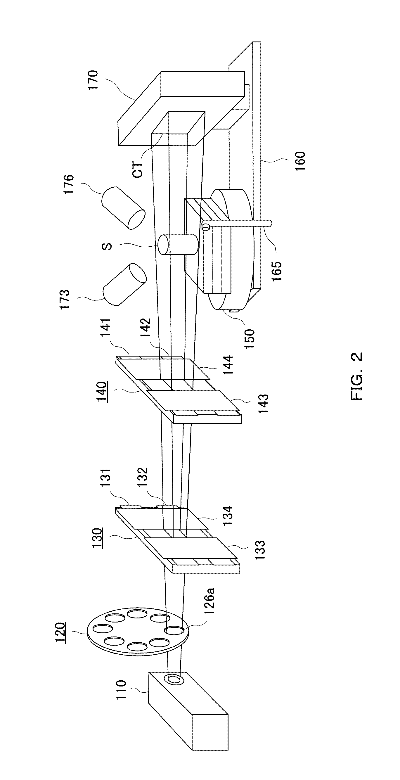
[0062]First, the upper and lower slits 131, 132, 141, and 142 and the left and right slits 133, 134, 143, and 144 are opened, and an interval between each slit is adjusted so that the sample S can be irradiated with the cone beam X-rays. Then, the entire sample S is subjected to cone beam X-ray CT. By using the cone beam, three-dimensional information of the entire sample can be grasped.

[0063]After the X-ray CT is finished, CT software is executed on a PC, X-ray CT data is used on the CT software to observe an X-ray CT image, and a location requiring component analysis is specified on the CT software. For example, a region of inter...


PUM

PropertyMeasurementUnit
applied voltageaaaaaaaaaa
thicknessaaaaaaaaaa

Abstract

There is provided an X-ray composite apparatus capable of performing, with one unit, X-ray CT and element analysis by fluorescent X-rays. The X-ray composite apparatus 100 includes an X-ray source 110 generating cone beam X-rays, a sample support 150 holding a sample S, collimator parts 130 and 140 capable of narrowing the cone beam X-rays to form parallel X-rays, depending on the intended use, between the X-ray source and the sample support 150, a two-dimensional detector 170 detecting the cone beam X-rays transmitted through the sample S, and a fluorescent X-ray detector 176 detecting fluorescent X-rays radiated from the sample S, and when the apparatus is used for X-ray CT, the apparatus irradiates the sample with the cone beam X-rays, while when the apparatus is used for fluorescent X-ray analysis, the apparatus irradiates the sample S with the parallel X-rays.

Description

BACKGROUND OF THE INVENTION[0001]1. Field of the Invention[0002]The present invention relates to an X-ray composite apparatus capable of performing, with one unit of apparatus, X-ray CT and structural analysis by X-ray diffraction or element analysis using fluorescent X-rays.[0003]2. Description of the Related Art[0004]X-ray CT is a technology of irradiating a subject with X-rays from the 360° periphery of the subject, recording, with a detector, transmission X-rays partially absorbed by the subject and decayed, and reconstructing an image. Moreover, the X-ray diffraction is a phenomenon in which the X-rays are diffracted by a crystal lattice. Until now, a technology combining the X-ray CT and the X-ray diffraction has been disclosed (See Patent Document 1 and Patent Document 2).[0005]Patent Document 1 proposes an X-ray CT apparatus using X-ray diffraction which achieves CT with high resolution by enlarging a projected image in radiation facilities. The X-ray CT apparatus described ...

Claims


Application Information

Patent Timeline
Patent Type & Authority Applications(United States)
IPC IPC(8): G01N23/04G01N23/207G01N23/223
CPCG01N23/046G01N23/223G01N2223/419G01N2223/076G01N23/207
Inventor SASAKI, KATSUNARIHARA, YUKIHIROAKIYAMA, KIYOSHI
Owner RIGAKU CORP
Why Eureka
Try Eureka