Stroboscopic interferometry with frequency domain analysis

a frequency domain analysis and interferometer technology, applied in the field of precision optical metrology instruments and methods, can solve problems such as significant errors, wavelength instability, and imaging interferometers

Active Publication Date: 2007-02-13
ZYGO CORPORATION
View PDF4 Cites 30 Cited by
  • Summary
  • Abstract
  • Description
  • Claims
  • Application Information

AI Technical Summary

Benefits of technology

[0011]The invention employs frequency-domain analysis (FDA) in combination with stroboscopic interferometry to overcome the issue of wavelength stability when using, e.g., a pulsed LED source. FDA obviates the need for wavelength stability by relating all surface height characteristics to the OPD scan rate, rather than the source wavelength.

Problems solved by technology

One potential complication in applying stroboscopic illumination to an imaging interferometer is wavelength instability.
Most interferometric systems depend on a stable wavelength, and may fail if the mean wavelength or other spectral properties of the source vary because of changes in environmental conditions or adjustments in illumination strength.
In coherence-scanning interferometers, the fringe contrast envelope often must be assumed to be of a particular functional form, such as Gaussian, in order to be accurate; and distortions of this envelope shape due to surface colors or unexpected or unusual source spectra can also lead to significant errors.
The wavelength of a pulsed LED can be particularly unstable and dependent on duty cycle.
In a conventional interferometer, a few nm change in effective wavelength on a sample having 100 mm steps could lead to several hundred nanometers of error.
Combined phase and coherence sensing techniques are often more sensitive to wavelength errors, with print-through of the interference fringes when incorrect wavelengths are used.

Method used


Image

  • Stroboscopic interferometry with frequency domain analysis
  • Stroboscopic interferometry with frequency domain analysis
  • Stroboscopic interferometry with frequency domain analysis

Examples


Embodiment Construction

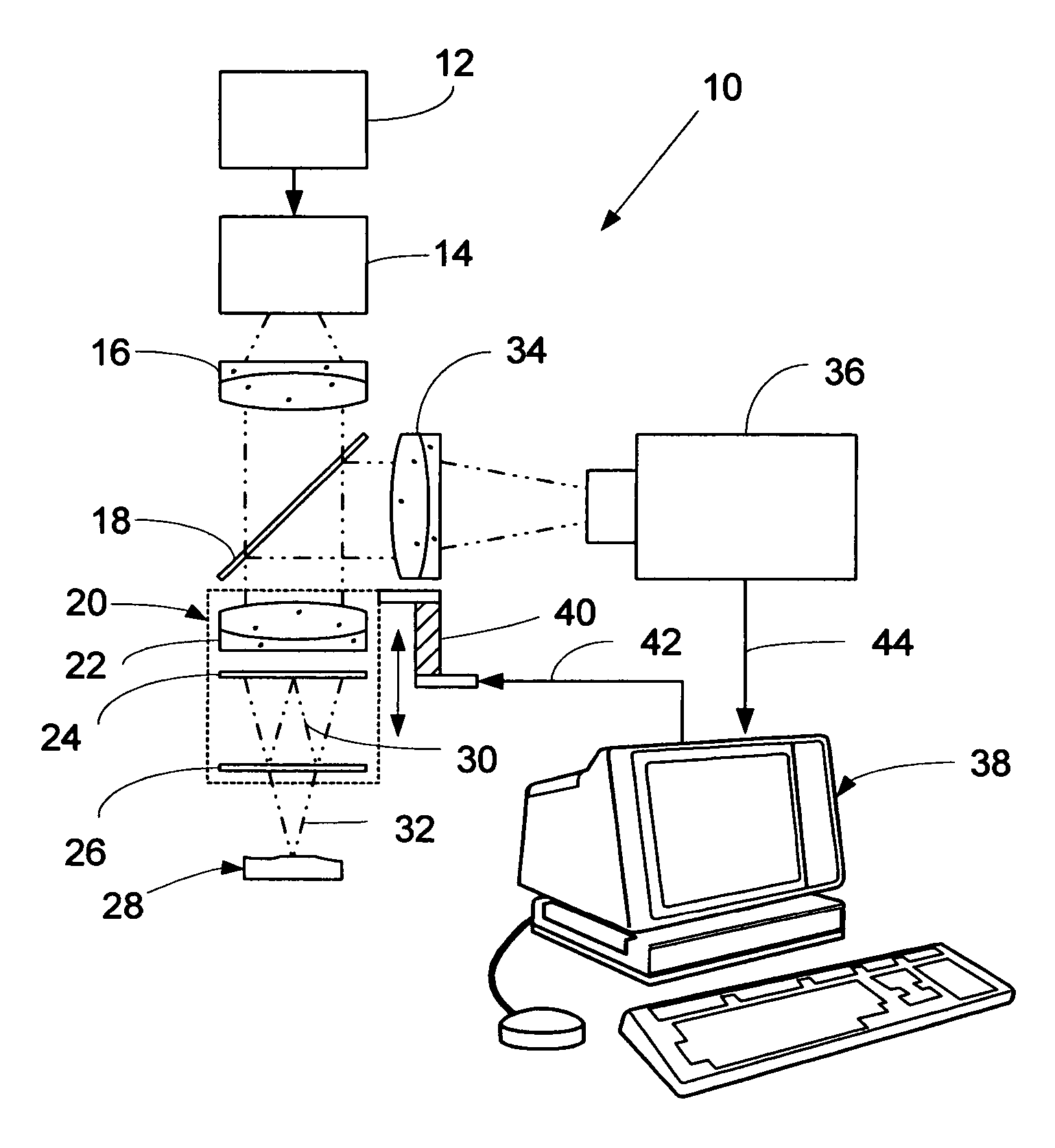
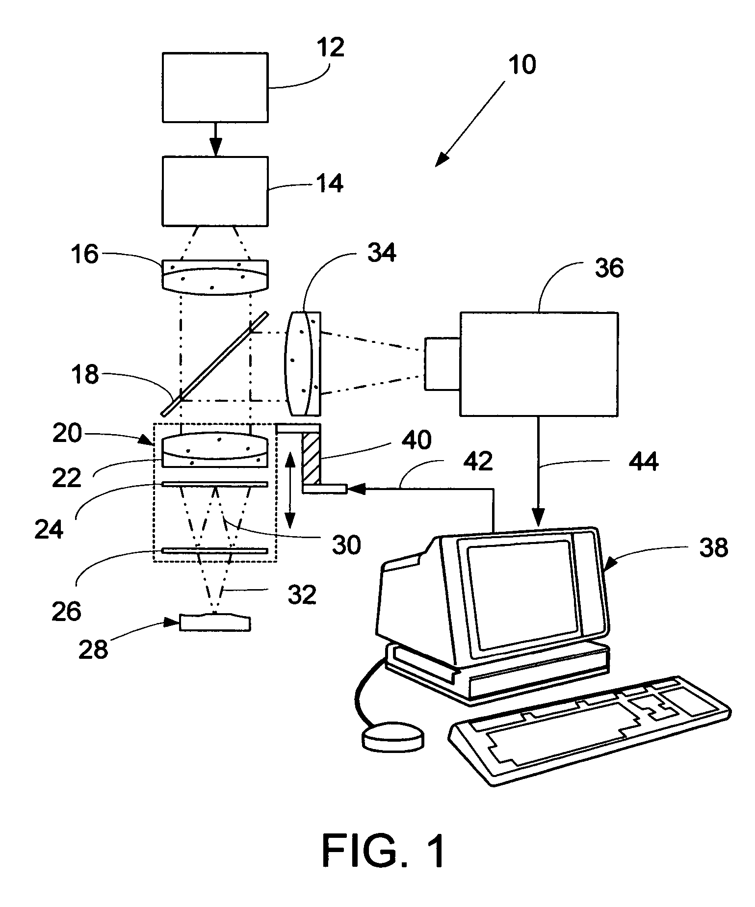
[0018]Reference is now made to FIG. 1 which shows an embodiment of the computer-based, stroboscopic interferometric microscope system (the “system”) of the invention employing FDA analysis to quantitatively measure the microscopic topography of a vibrating object such as, but not limited to, for example, a MEMS or SAW device.

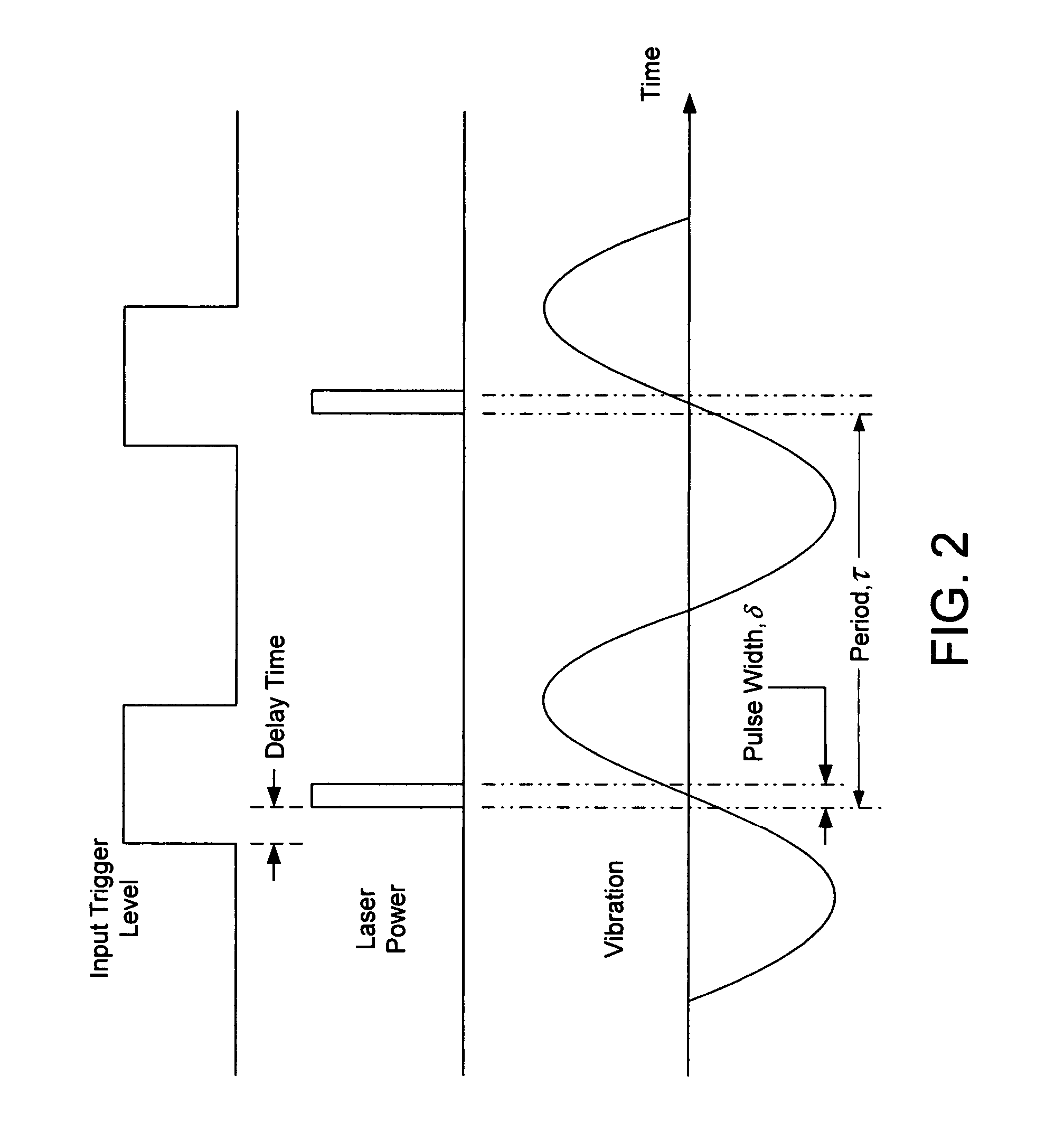
[0019]As seen in FIG. 1, the inventive system, designated generally at 10, comprises a source 14 that is modulated by a signal generator 12, for example, an arbitrary waveform generator (AWG) to provide a series of pulses of illumination. For example, the embodiment of FIG. 1 supplies, e.g., a sequence of pulses of constant pulse width δ at a uniform spacing τ as shown in FIG. 2. The source 12 may be any suitable type capable of being modulated to provide pulses having durations that are sufficiently short to apparently “freeze” fringes. Suitable sources include light emitting diodes (LEDs), laser diodes (LDs), and white light sources. Preferably LEDs with spect...


PUM


Abstract

A computer-based stroboscopic interferometric microscope system for measuring the topography of a microscopic vibratory object includes an interferometric microscope equipped with a multiple-color (e.g., LED) or white-light source, a mechanical scanning apparatus for varying the optical path difference between the vibratory object and a reference surface, a camera having a two-dimensional detector array, and digital signal processing apparatus for determining surface height from interference data. Interferograms for each of the detector image points in the field of view are generated simultaneously by scanning the object in a direction approximately perpendicular to the object surface illuminated stroboscopically while recording detector data in digital memory. Recorded interferograms for each image point are then transformed into the spatial frequency domain by Fourier analysis, and the surface height for each corresponding object surface point is obtained by examination of the complex phase as a function of spatial frequency. A complete three-dimensional image of the object surface is then constructed from the height data and corresponding image plane coordinates. The three-dimensional image may be presented on a display or hard copy or written to a storage medium.

Description

CROSS REFERENCE TO RELATED APPLICATION[0001]This application claims the benefit of priority from U.S. Provisional Patent Application No. 60 / 486,204 filed in the name of Peter J. deGroot on Jul. 10, 2003 with the title “STROBOSCOPIC INTERFEROMETRY WITH FREQUENCY DOMAIN ANALYSIS”, the entire contents of which are incorporated herein by reference.FIELD OF THE INVENTION[0002]This invention relates generally to precision optical metrology instrumentation and methods for imaging and analysis of microscopic vibrating surfaces and, more particularly, to stroboscopic interferometric methods and stroboscopic interferometric microscope systems for three-dimensional topographical surface profiling of moving object surfaces.BACKGROUND OF THE INVENTION[0003]A stroboscope is a common tool for “freezing” the apparent motion e.g. of a vibration object. It produces the optical effect of stopping or slowing down an object to allow you to observe and analyze the object's motion.[0004]Stroboscopic illum...

Claims


Application Information

Patent Timeline
Patent Type & Authority Patents(United States)
IPC IPC(8): G01B11/02G01B9/02G01B11/24G01H9/00
CPCG01H9/002G01B11/2441
Inventor DEGROOT, PETER J.
Owner ZYGO CORPORATION
Why Eureka
Try Eureka