Method and system for determining origin of optical signal quality degradation

a technology of optical signal quality and origin, applied in multiplex communication, transmission monitoring, instruments, etc., can solve the problems of insufficient single receiving system to handle a given bit rate, difficult application of inability to identify the section between optical amplifier repeater system at which the fault occurs, etc., to achieve high reliability, low cost, and large communication capability

Inactive Publication Date: 2007-04-03
NIPPON TELEGRAPH & TELEPHONE CORP
View PDF10 Cites 11 Cited by
  • Summary
  • Abstract
  • Description
  • Claims
  • Application Information

AI Technical Summary

Benefits of technology

[0012]The present invention is implemented to solve the foregoing problems. Therefore, an object of the present invention is to provide a method and system for determining the origin of optical signal quality degradation contributing to implementing a low cost, highly reliable optical network capable of accommodating multimedia services that have large communication capability per service, and a variety of signal formats and signal bit rates.
[0026]The foregoing configuration can monitor the degradation factor of the optical signal quality. Thus, it can implement a low cost, highly reliable optical network capable of accommodating multimedia services that have large communication capability per service, and a variety of signal formats and signal bit rates.

Problems solved by technology

Therefore, a single receiving system is not enough to handle a given bit rate, signal format or modulation method.
Accordingly, it is difficult to apply it to the optical amplifier repeater system considering the cost efficiency.
For example, even if a network fault is detected, the section between the optical amplifier repeater systems, at which the fault occurs, cannot be identified.
However, although the averaged Q-factor parameter in the conventional example is sensitive to the degradation in the optical signal-to-noise ratio and the waveform distortion due to the chromatic dispersion, it cannot discriminate their causes.

Method used


Image

  • Method and system for determining origin of optical signal quality degradation
  • Method and system for determining origin of optical signal quality degradation
  • Method and system for determining origin of optical signal quality degradation

Examples


first embodiment

(First Embodiment)

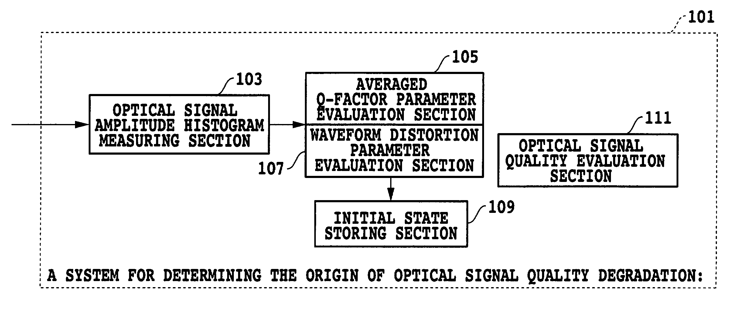
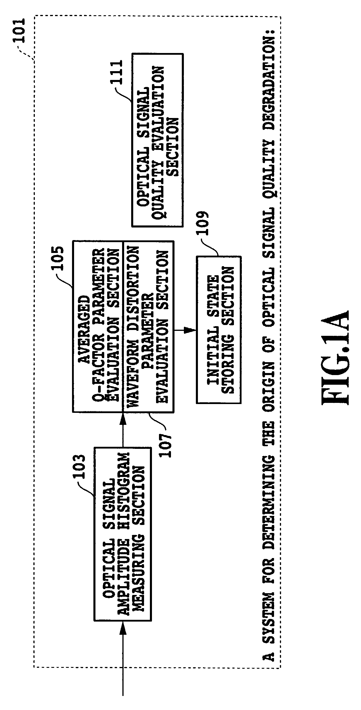
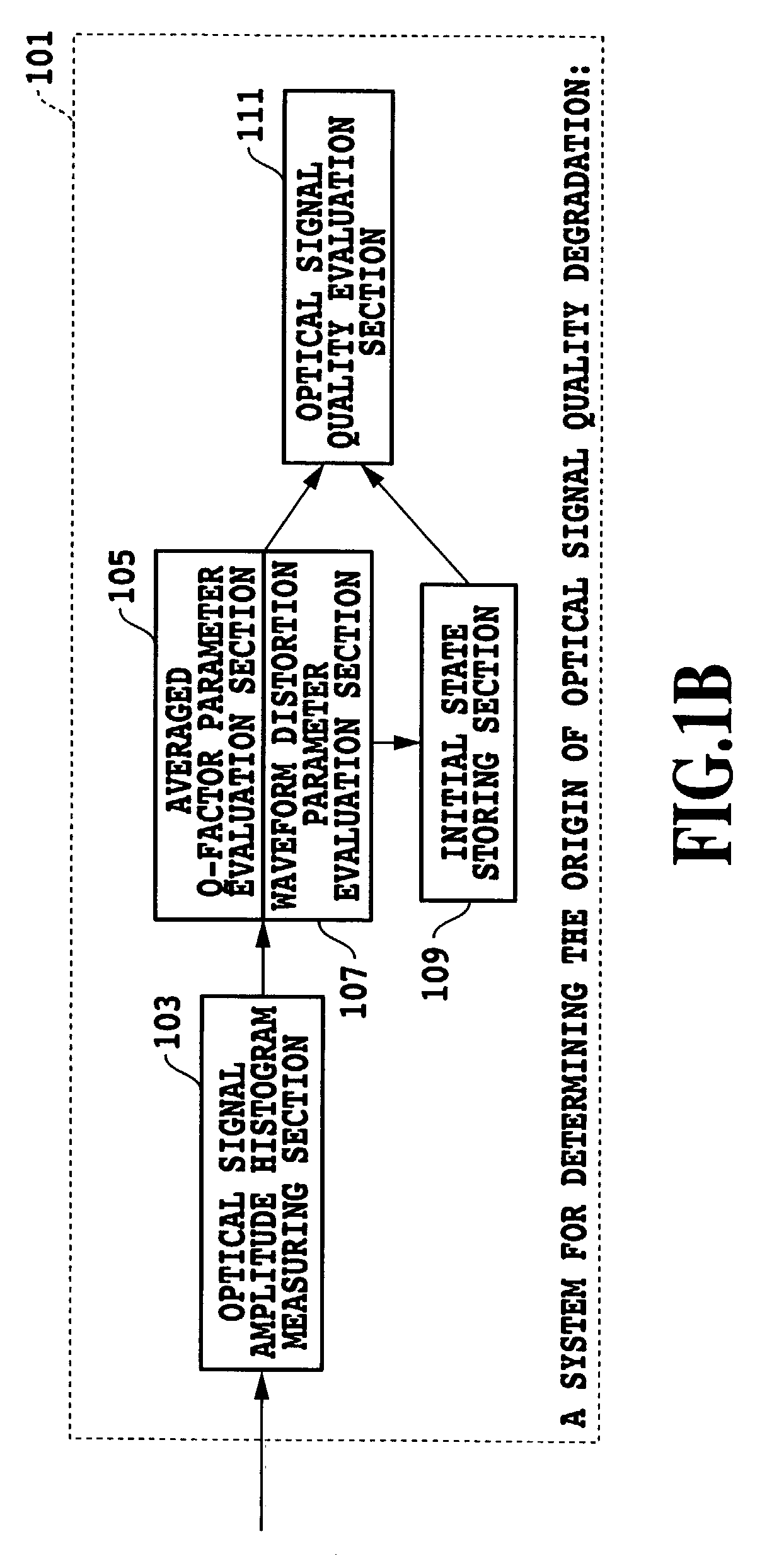
[0046]FIGS. 1A and 1B show a system for determining the origin of optical signal quality degradation of a first embodiment in accordance with the present invention. The system for determining the origin of optical signal quality degradation 101 of the present embodiment comprises an optical signal amplitude histogram measuring section 103, an averaged Q-factor parameter evaluation section 105, a waveform distortion parameter evaluation section 107, an initial state storing section 109 and an optical signal quality evaluation section 111.

[0047]The optical signal amplitude histogram measuring section 103 obtains an optical amplitude histogram from the optical signal under measurement. The averaged Q-factor parameter evaluation section 105 obtains the averaged Q-factor parameter which is the optical signal quality parameter, from the optical signal amplitude histogram. The waveform distortion parameter evaluation section 107 obtains the waveform distortion parameter w...

second embodiment

(Second Embodiment)

[0098]FIGS. 12A and 12B show a system for determining the origin of optical signal quality degradation of a second embodiment in accordance with the present invention. The system for determining the origin of optical signal quality degradation 1201 of the present embodiment comprises an optical splitter 1203, an optical signal amplitude histogram measuring section 1205, an optical signal to optical noise power measuring section 1207, an averaged Q-factor parameter evaluation section 1209, an optical signal-to-noise ratio parameter evaluation section 1211, an initial state storing section 1213, and an optical signal quality evaluation section 1214.

[0099]The optical splitter 1203 splits the optical signal under measurement. The optical signal amplitude histogram measuring section 1205 obtains the optical signal amplitude histogram from a first optical signal under measurement after the splitting. The optical signal to optical noise power measuring section 1207 measu...

third embodiment

(Third Embodiment)

[0114]FIGS. 15A and 15B show a system for determining the origin of optical signal quality degradation of a third embodiment in accordance with the present invention. In FIGS. 15A and 15B, the same reference numerals designate the same or like portions to those of FIGS. 12A and 12B. The system for determining the origin of optical signal quality degradation 1501 of the present embodiment comprises an optical splitter 1203, an optical signal amplitude histogram measuring section 1205, an optical signal to optical noise power measuring section 1207, an averaged Q-factor parameter evaluation section 1503, a waveform distortion parameter evaluation section 1505, an optical signal-to-noise ratio parameter evaluation section 1211, an initial state storing section 1213, and an optical signal quality evaluation section 1214.

[0115]The optical splitter 1203 splits the optical signal under measurement. The optical signal amplitude histogram measuring section 1205 obtains the ...


PUM


Abstract

A monitoring system includes first and second evaluation sections for obtaining an averaged Q-factor parameter and a waveform distortion parameter from an optical signal amplitude histogram collected from optical signals under measurement. The monitoring system further includes a third evaluation section for determining both averaged Q-factor parameter and waveform distortion parameter, and for making a decision as to whether the main factor of the optical signal quality degradation is waveform distortion or not by comparing the averaged Q-factor parameter and waveform distortion parameter with their initial values or initial characteristics which are obtained when no optical signal quality degradation is present.

Description

[0001]This application is based on Japanese Patent Application No. 2001-214212 filed Jul. 13, 2001 in Japan, the content of which is incorporated hereinto by reference.BACKGROUND OF THE INVENTION[0002]1. Field of the Invention[0003]The present invention relates to a method and system for determining the origin of optical signal quality degradation in optical communication.[0004]2. Description of the Related Art[0005]The point-to-point or point-to-multipoint communication in the optical communication up to the present time bundles signals by applying Optical Time Division Multiplexing (OTDM) to frames offered by a synchronous network.[0006]Such OTDM employs a transmission system such as Synchronous Optical Network (SONET) / Synchronous Digital Hierarchy (SDH). The SONET / SDH transmission system defines overhead to perform efficient signal transmission (Reference [1]: ITU-T Recommendation G707), in which the overhead executes parity check called bit interleaved parity between repeaters a...

Claims


Application Information

Patent Timeline
Patent Type & Authority Patents(United States)
IPC IPC(8): H04B10/08H04B10/00H04B10/02H04B10/079
CPCH04B10/07951H04B10/07953
Inventor SHAKE, IPPEITAKARA, HIDEHIKOUCHIYAMA, KENTARO
Owner NIPPON TELEGRAPH & TELEPHONE CORP
Why Eureka
Try Eureka