Eureka AIR delivers breakthrough ideas for toughest innovation challenges, trusted by R&D personnel around the world.

Building truss having a connector with an integral mounting to supporting structure

a technology of connecting rods and supporting structures, which is applied in the direction of girders, mechanical devices, nails, etc., can solve the problems of poor quality control, large variation in quality and structural strength of field connections, and difficulty in designing satisfactory uplift connections for modular home builders, so as to save setup crews time, reduce call-backs and design rejections, and fasten quickly and efficiently

Active Publication Date: 2007-04-10
UFP IND INC
View PDF9 Cites 13 Cited by
  • Summary
  • Abstract
  • Description
  • Claims
  • Application Information

AI Technical Summary

Benefits of technology

[0009]A strong, “clean” pre-engineered connection can be built integral with the truss at the time of truss manufacture. This saves home building setup crews from making job-specific connections between roof truss components which may include cutting numerous wood blocks and driving numerous mechanical fasteners (nails and staples) to attempt to provide a finished field connection. Rather, the connector described herein is a pre-engineered connection that can readily be evaluated by structural engineers and building inspectors for performance. The integral connection saves setup crews time when making final connections. Due to the pre-engineered nature of the connector, building inspectors more readily accept the fastening method, thereby resulting in fewer call-backs and design rejections by building inspectors.
[0010]Because the connector is installed integral to the truss at the time of truss manufacture, the connector can be shipped with a preassembled truss and allows a home setup crew to quickly and efficiently fasten sub-components of a roof truss (such as a swing-down knee-wall connection to a king post, and also to attach a swing-down knee wall in a Cape Cod-style design. By providing this integral connection, manufacturers are able to set up their houses more expeditiously with a much higher-quality connection between the knee wall and king post and / or the knee wall and the bottom chord of a roof truss.

Problems solved by technology

Modular home builders have difficulty designing a satisfactory uplift connection between a knee wall and a kingpost or a bottom chord of a roof truss for a modular home.
These methods have very little quality control and result in field connections with widely varying levels of quality and structural strength.
Building inspectors often become concerned about the lack of consistency in the design and application of these field connections on modular trusses.
Many building inspectors have deemed these connection methods unsatisfactory.

Method used


Image

  • Building truss having a connector with an integral mounting to supporting structure
  • Building truss having a connector with an integral mounting to supporting structure
  • Building truss having a connector with an integral mounting to supporting structure

Examples


second embodiment

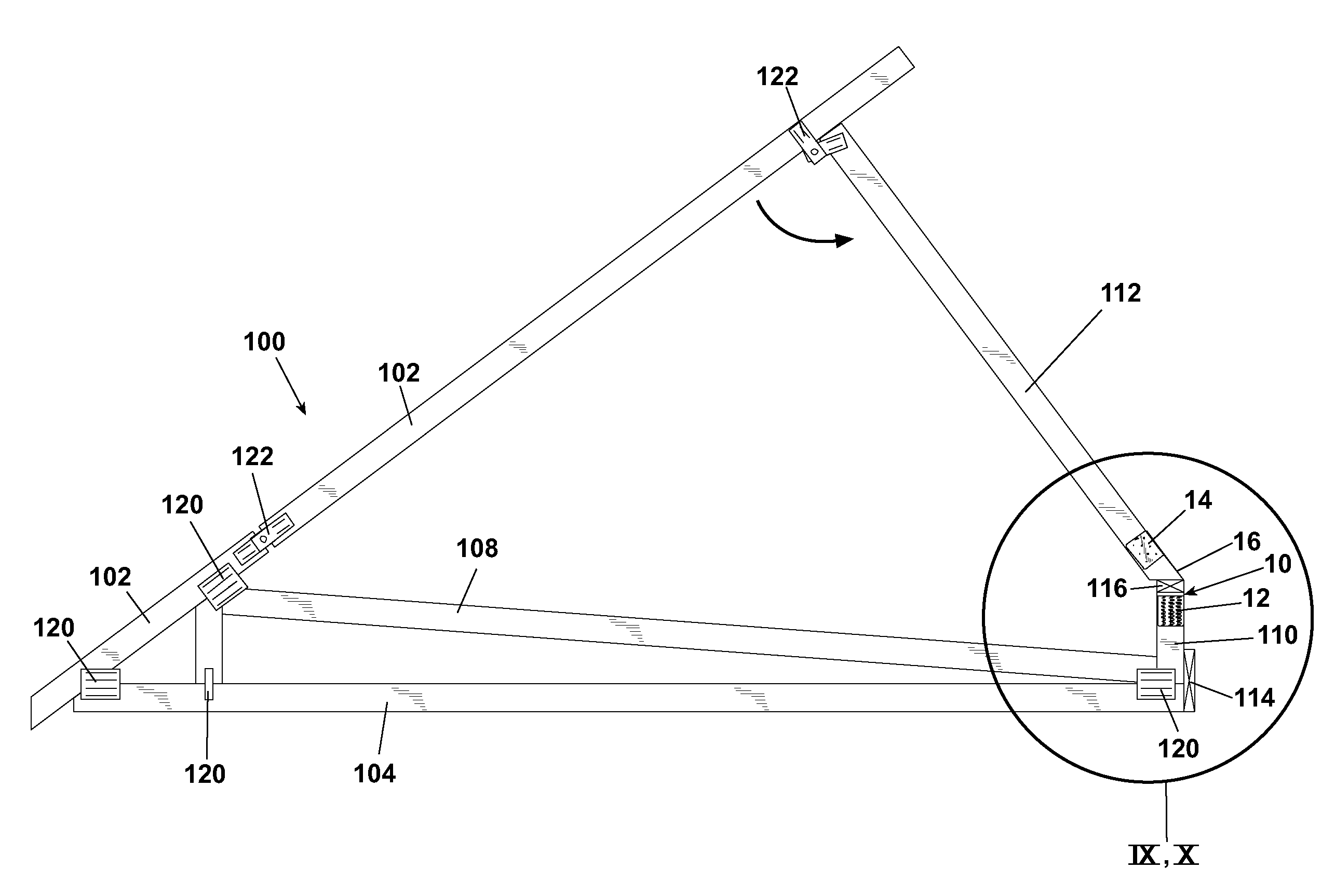
[0090]An example of a roof truss 100 employing the connector 10 shown in FIGS. 20–23 is shown in a collapsed state and FIGS. 24–26 and in an erected state in FIGS. 27–29. The construction of this roof truss 100 shown in FIGS. 24–29 is very similar to that shown in FIGS. 14–19 except that the kingpost 110 has been eliminated in favor of a direct connection by the connector 10 to the bottom chord 104 in each case. As can best be seen in FIGS. 24–26, the first engagement portion 12 of the connector 10 is connected directly to a vertical surface of the bottom chord 104 in a manner consistent with that described previously with respect to the mounting of the first engagement portion 12 to an upper portion of the kingpost 110.

[0091]The roof truss 100 would thereby be shipped to an on-site installation location with the connector 10 extending upwardly therefrom. Turning to FIGS. 27–29, the upper top chord 102 is swung about the first hinge plate 122 and the knee wall 112 is positioned into...

third embodiment

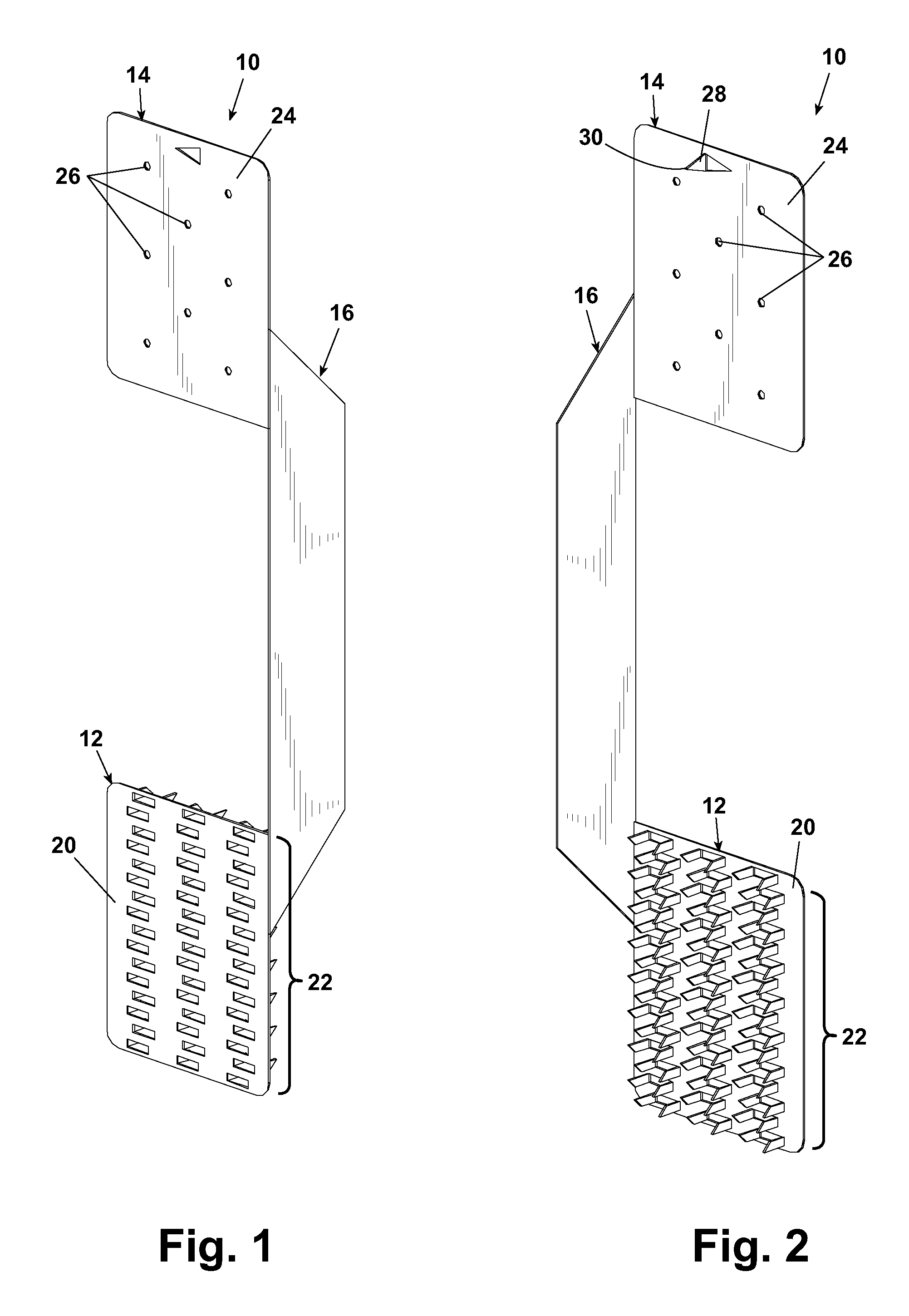
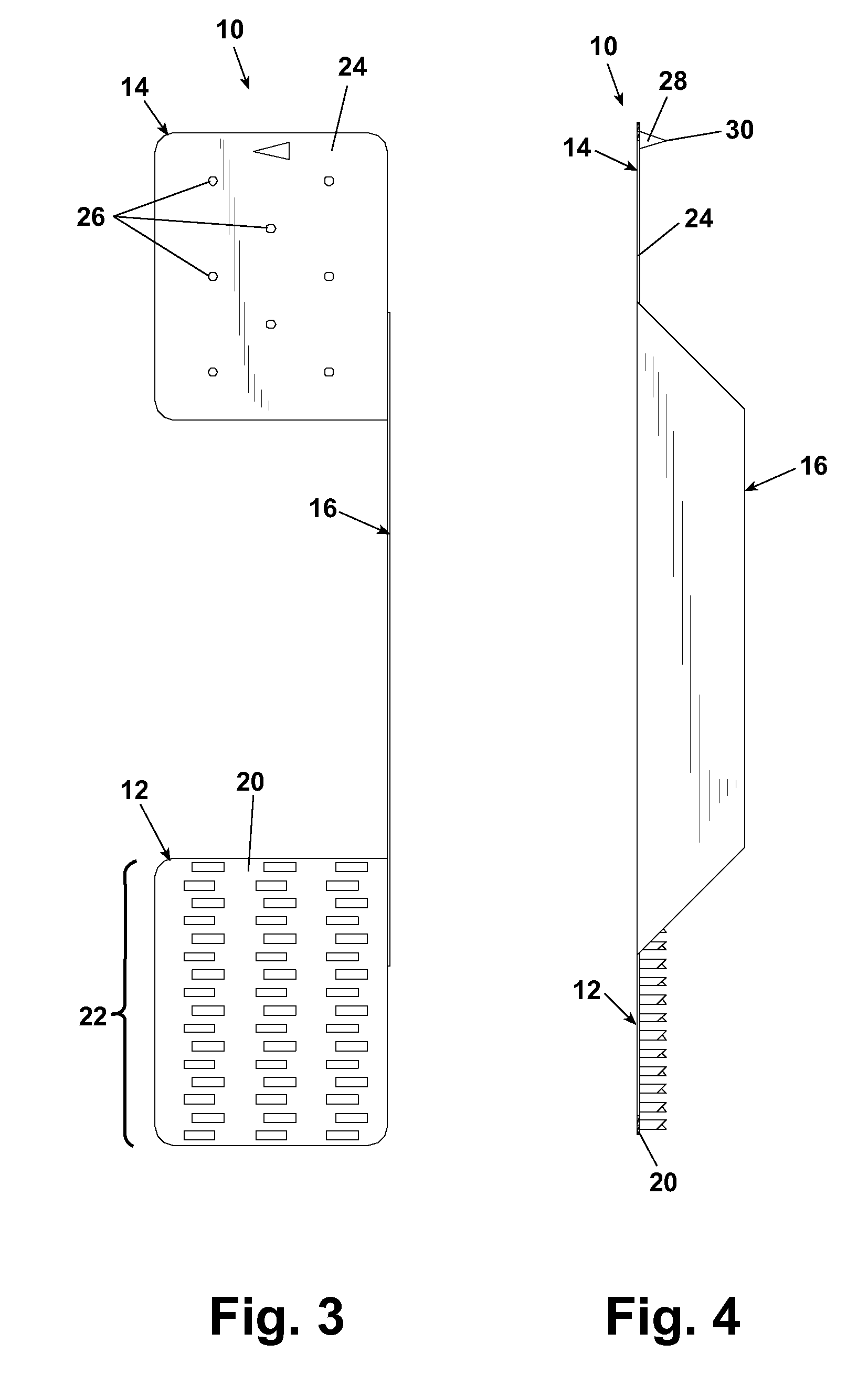
[0093]The first and second engagement portions 12 and 14 are maintained in generally linear alignment with one another as the angular webs 16b and 16c laterally offset the elongated body 16a from this linear alignment, creating a recess 16d between the web portions 16a, 16b and 16c and between the first and second engagement portions 12 and 14. It will be understood that it is not critical to this invention that the first and second engagement portions 12 and 14 be maintained in linear alignment and that different configurations and alignments of the first and second engagement portions are contemplated without departing from the scope of this invention. This configuration of the connector 10 is useful in areas where an internal chord member of a roof truss creates an obstruction to the interconnection of a pair of roof truss chords, in that the side step configuration of the connector 10 can be used to conveniently traverse an obstructing and / or intervening chord member as describe...

fifth embodiment

[0098]This configuration of the connector 10 is useful in areas where an internal chord member of a roof truss creates an obstruction to the interconnection of a pair of roof truss chords, in that the hinged portion 16e of the connector 10 can be used to conveniently pivot one of the engagement portions 12 and / or 14 to traverse an obstructing and / or intervening chord member to bring one of the engagement portions into alignment with another chord of the roof truss for attachment as described below with respect to FIGS. 42–44.

[0099]An example of a roof truss 100 employing the fifth embodiment of the connector 10 shown in FIGS. 38–41 is shown FIGS. 42–44. It will be understood that the roof truss 100 of FIGS. 42–44 can be collapsed and erected in similar manner to the roof trusses shown and described with respect to the earlier embodiments in FIGS. 1–37. As can best be seen in FIGS. 42–44, the first engagement portion 12 of the third embodiment of the connector 10 is connected directl...


PUM


Abstract

A truss and connector assembly for use in housing structures is shown. The connector provides a direct and integral mounting of the truss to the wall studs to provide increased mounting strength for the roof assembly to the side walls of a structure. A connector according to the invention can be integrally preassembled to a truss at one location and connected to remaining portions of the truss at a separate location.

Description

CROSS REFERENCE TO RELATED APPLICATIONS[0001]This application claims the benefit of U.S. Provisional Application Ser. No. 60 / 319,658, filed on Oct. 29, 2002.BACKGROUND OF INVENTION[0002]1. Field of the Invention[0003]This invention relates to a connector for a truss assembly for the framework of a building and, more particularly, to a preassembled truss having a connector for securing internal chords of a truss to one another. In one particular aspect, the invention is particularly beneficial for preassembled roof trusses which are manufactured at a facility and shipped to a home builder's facility for installation on a roof truss and / or to a worksite for installation, such as in a modular housing structure.[0004]2. Description of the Related Art[0005]The structural framework of a conventional structure typically comprises a plurality of wall studs spaced from one another, a horizontal top plate extending along the top edge of each of the wall studs and a plurality of roof trusses m...

Claims


Application Information

Patent Timeline
Patent Type & Authority Patents(United States)
IPC IPC(8): E04B1/32
CPCE04C3/005E04C3/17F16B15/0046
Inventor FREEMAN, KEVIN WESLEYSIROWATKA, JOHN
Owner UFP IND INC
Why Eureka
Eureka Blog
Learn More