Combustion pressure sensor and glow plug including the same

a technology of combustion pressure sensor and glow plug, which is applied in the direction of instruments, lighting and heating apparatus, machines/engines, etc., can solve the problems of non-uniform pre-load on the inner wall of the case to the piezoelectric element, and the noise produced by the top end-facing end surface of the inner wall of the case, so as to reduce the generation of the noise caused by the rocking, reduce the size of the internal combustion engine, and improve the sensitivity

Inactive Publication Date: 2007-04-10
NGK SPARK PLUG CO LTD
View PDF14 Cites 13 Cited by
  • Summary
  • Abstract
  • Description
  • Claims
  • Application Information

AI Technical Summary

Benefits of technology

[0013]As recited in the first embodiment, either one of the pressing portion and the supporting portion is formed with a second opening which is different from the first opening. As described above, if the first opening is formed in the pressing portion or the supporting portion, the rigidity of the pressing portion or the supporting portion may partially decrease due to the presence of the first opening, and a pre-load exerted on the piezoelectric elements may be non-uniform. If a force in a rocking direction is additionally exerted thereon, the absolute amount of the positive charge and the negative charge generated in one piezoelectric element and the other piezoelectric element, partitioned from each other by a plane containing an axis, differs from each other. However, due to the presence of the second opening, the absolute amounts can be equal to each other. Therefore, even if the combustion pressure sensor of the present invention receives a force in a rocking direction, it can still reduce the noise caused by the rocking.
[0014]When the second opening is formed as described above, as is recited in the second embodiment, the second opening is preferably formed in an area which is opposite to the area having the first opening in the pressing portion or the supporting portion and is partitioned therefrom by a straight line intersecting the direction from the axis toward the first opening and containing the axis. In this structure, the load applied to the piezoelectric element by the area formed with the first opening and the load applied to the piezoelectric element by the area formed with the second opening is balanced so as to be equal to each other. That is, when one of the areas has both a portion with low rigidity and a portion with high rigidity, the pre-load applied to the piezoelectric element be comes non-uniform in this area. Since the load in the area opposed to this area is also similarly made to be non-uniform, the absolute amounts of the positive and negative charges can be made to be equal in these areas. Therefore, even if rocking is applied to the combustion pressure sensor, the generation of noises caused by the rocking can be reduced.
[0015]As means for making the degree of the lowering in the rigidity of the case to be equal, the structure recited in the third embodiment may also be employed. The straight line passing through the axis and containing the direction from the axis toward the first opening, and the straight line intersecting said straight line and passing through the axis depict two straight lines intersecting on the axis on the plane where their images are projected. Since the case is structured to be bilaterally symmetrical with respect to both of these two straight lines, the degree of lowering in the rigidity of the case can be made to be uniformly equal to each other. Even if a force is applied from a rocking direction, the absolute amounts of the positive and negative charges that the applied force generates in the piezoelectric elements can still be equal to each other. Therefore, reduction of noises, or suppression of the generation of noise caused by rocking of the combustion pressure sensor, becomes possible.
[0016]Alternatively, the structure recited in the fourth embodiment may be employed. That is, in the case in which an image is projected onto a plane intersecting the axis, an arbitrary opening which is either one of the first opening or the second opening extending from the axis, and an opening which has the same shape as said opening and constitutes a pair with said opening on the opposite side of centered on the position of the axis are formed. In this manner, when the combustion pressure sensor is viewed at its arbitrary cross section containing the axis, the left and right portions of the piezoelectric element centered on the axis are as a result subjected to the same pre-load. Thus, the absolute amounts of the positive and negative charges generated in the piezoelectric elements by force in the rocking direction can be equal to each other. As a result, even if rocking is applied to the combustion pressure sensor, the generation of noises caused by the rocking can be reduced.
[0018]In addition, the glow plug of the invention recited in the fifth embodiment includes a combustion pressure sensor in which a supporting portion is provided at a rear end side of the main metal fitting, and inside the supporting portion, a pressing member provided at a rear end side of the center shaft as a pressure transmitting member, piezoelectric elements, and electrodes are accommodated. Specifically, the pressing portion displaces as the center shaft displaces in accordance with the combustion pressure, and the pre-load applied to the piezoelectric element between the pressing portion and the supporting portion increases and decreases. The total amount of the positive or negative charge generated by the increase and decrease in the pre-load is obtained as a magnitude of the combustion pressure. By the way, the glow plug is directly mounted onto the internal combustion engine, and receives a rocking influence cased by vibration involved in the actuation of the internal combustion engine. By use of the combustion pressure sensor recited in either one of the first embodiment to the fourth embodiment as a combustion pressure sensor, the generation of the noise caused by the rocking can be reduced in a structure where the signal wire connected to the electrode accommodated in the supporting portion is taken out of the supporting portion via the first opening. As a result, the combustion pressure can be sensed with excellent sensitivity. Further, the glow plug assists ignition by use of the heater member exposed inside the combustion room. By employing a structure in which the center shaft is mechanically linked to the heater member and the change in stress caused by the combustion pressure to which the heater member has been subjected via the center shaft is sensed by the combustion sensor, there is no need to prepare either locations for assembling a heater for assisting ignition or a combustion pressure sensor. As a result, the internal combustion engine can be downsized.
[0019]On the other hand, the glow plug of the invention recited in the sixth embodiment includes a combustion pressure sensor structured so that the pre-load applied to the piezoelectric element between the supporting portion provided at the rear end side of the main metal fitting and the pressing portion provided at the rear end side of the center shaft decreases as the pressing portion displaces commensurately with the displacement of the center shaft according to the combustion pressure, and the amount of the charge generated at this time is obtained as the magnitude of the combustion pressure. Even in a structure such as this glow plug in which the first opening for taking out the signal wire is provided at the side of the pressing portion, the generation of noise caused by rocking can be reduced and the combustion pressure can be sensed with excellent sensitivity, as in the case described above. Then, as in the case described above, by employing a structure including the combustion pressure sensor and the heater for assisting ignition integrated into one piece unit, the internal combustion engine can be downsized.

Problems solved by technology

There may be a case where this superimposed force produces a noise and exerts an influence on a sensor output.
If the rigidity of the case is partially low, and thus the rigidity of the entire case is non-uniform, the pre-load exerted by the top end-facing end surface of the inner wall of the case to the piezoelectric element may also accordingly be non-uniform.
In this case, when a force is applied in a rocking direction, there is a danger that a difference may arise in the absolute amounts of charges generated at one and the other sides of the piezoelectric element partitioned from each other by said plane, and that such a difference may cause noises.

Method used


Image

  • Combustion pressure sensor and glow plug including the same
  • Combustion pressure sensor and glow plug including the same
  • Combustion pressure sensor and glow plug including the same

Examples


example 1

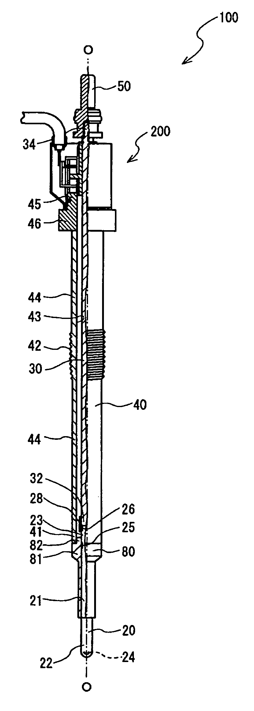
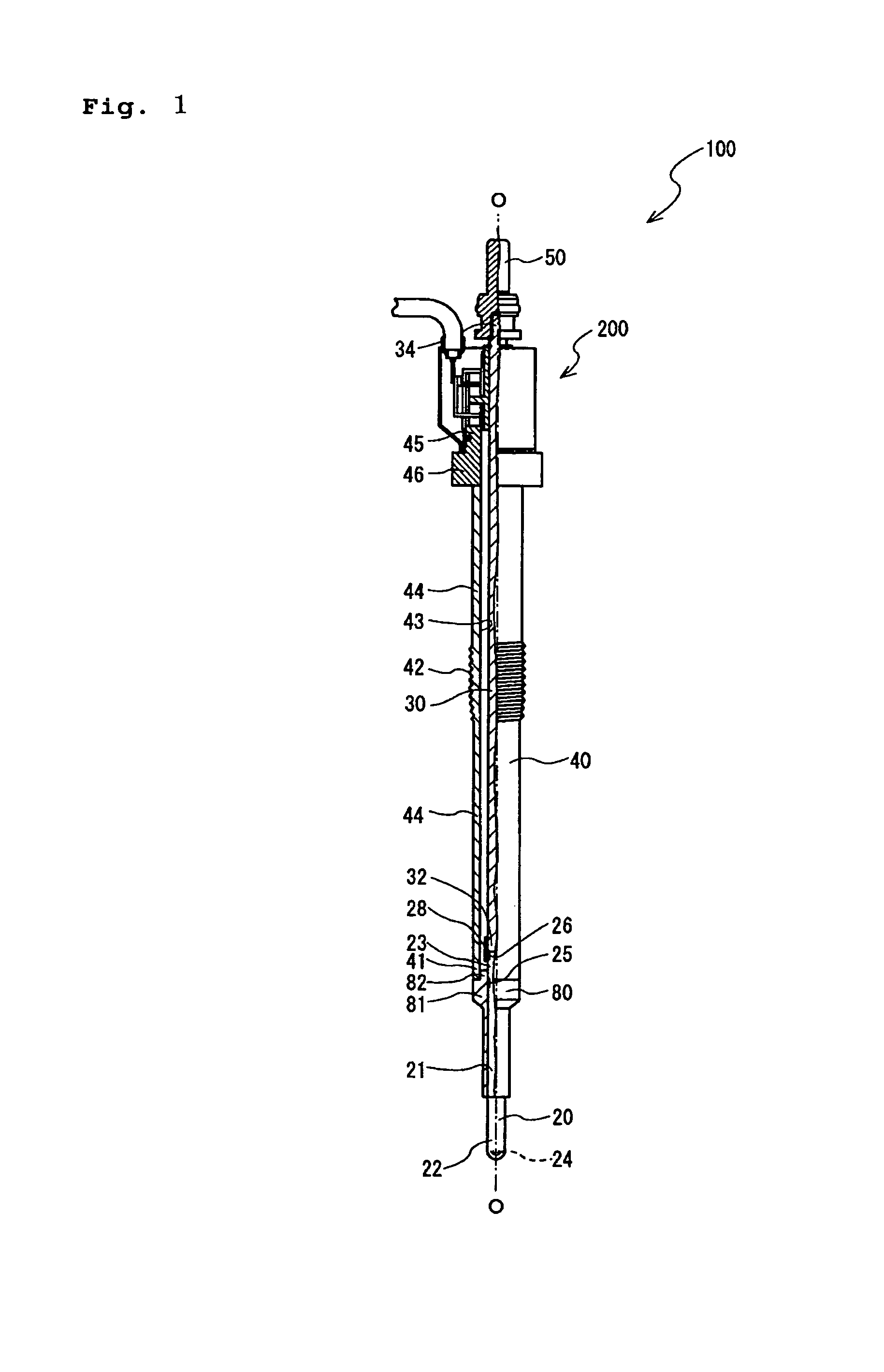
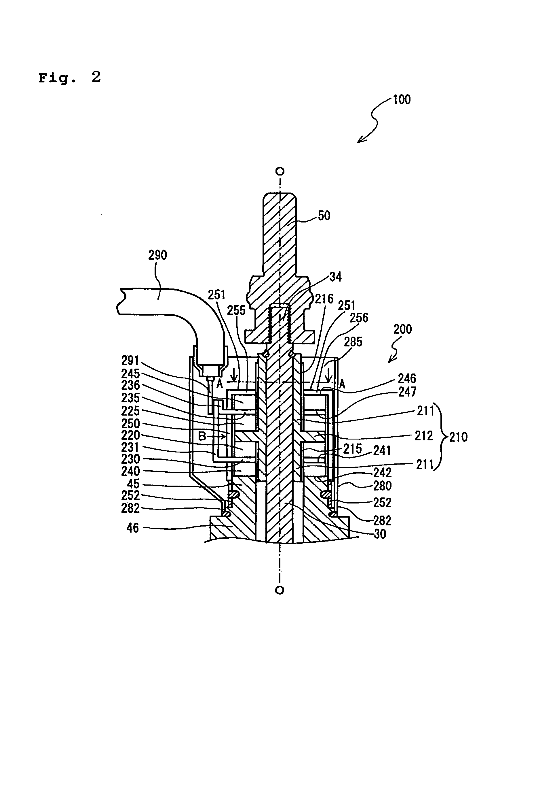
[0065]In order to confirm the effect described above, aglow plug 100 was assembled on to an internal combustion engine (not shown), and an output from a combustion pressure sensor 200 was checked. First of all, a glow plug (sample 1) including a case 250 formed with a slit 255, but not a slit 256 which has conventionally been employed, and a glow plug 100 (sample 2) of this embodiment, as heretofore described, were prepared. Then, the combustion pressure of the internal combustion engine that was used for testing was measured by use respectively of sample 1 and sample 2. At this time, the measurement was conducted in a state where the magnitude of the combustion pressure was adjusted by use of a reference pressure sensor (model 6052A, manufactured by KISTLER) so as to be identical in a case where an evaluation test for the sample 1 was conducted and a case where an evaluation test for the sample 2 was conducted.

[0066]More specifically, an output (an output that makes the signal wire...


PUM


Abstract

To provide a combustion pressure sensor capable of reducing noises generated by the force in a rocking direction by making uniform the stress exerted onto the piezoelectric element; and a glow plug having the same.

Description

FIELD OF THE INVENTION[0001]The present invention relates to a combustion pressure sensor for sensing the change in the combustion pressure in an internal combustion engine, and a glow plug for assisting the start of an internal combustion engine, which glow plug integrally includes the combustion pressure sensor.BACKGROUND OF THE INVENTION[0002]A glow plug, for assisting the start of an internal combustion engine, is known which integrally includes a combustion pressure sensor for sensing a combustion pressure of an internal combustion engine. In such a glow plug, a heater member, that is disposed at a top end side thereof and that generates heat when energized, is exposed inside the internal combustion engine. The combustion pressure acting on the heater member is transmitted to a piezoelectric element (i.e., a pressure-sensing element) for sensing a combustion pressure via a center shaft. The piezoelectric element is accommodated in a cylindrical casing (housing) at a rear end si...

Claims


Application Information

Patent Timeline
Patent Type & Authority Patents(United States)
IPC IPC(8): G01M15/00
CPCF23Q7/001G01L23/10G01L23/22G01L23/222F02P19/028F23Q2007/002F02P19/00F23Q7/00G01L23/00
Inventor YAMADA, TATSUNORIYAMADA, YUICHIHOTTA, NOBUYUKI
Owner NGK SPARK PLUG CO LTD
Why Eureka
Try Eureka