Front-accessible bevel locking system
a technology of bevel locking and front access, which is applied in the field of tilt locking mechanisms for power tools, can solve the problems of inaccessible location of conventional bevel locking mechanisms, inconvenience and threat to the safety of users of conventional power tools, and achieve the effect of increasing or decreasing the pressure applied and increasing the tension
- Summary
- Abstract
- Description
- Claims
- Application Information
AI Technical Summary
Benefits of technology
Problems solved by technology
Method used
Image
Examples
first embodiment
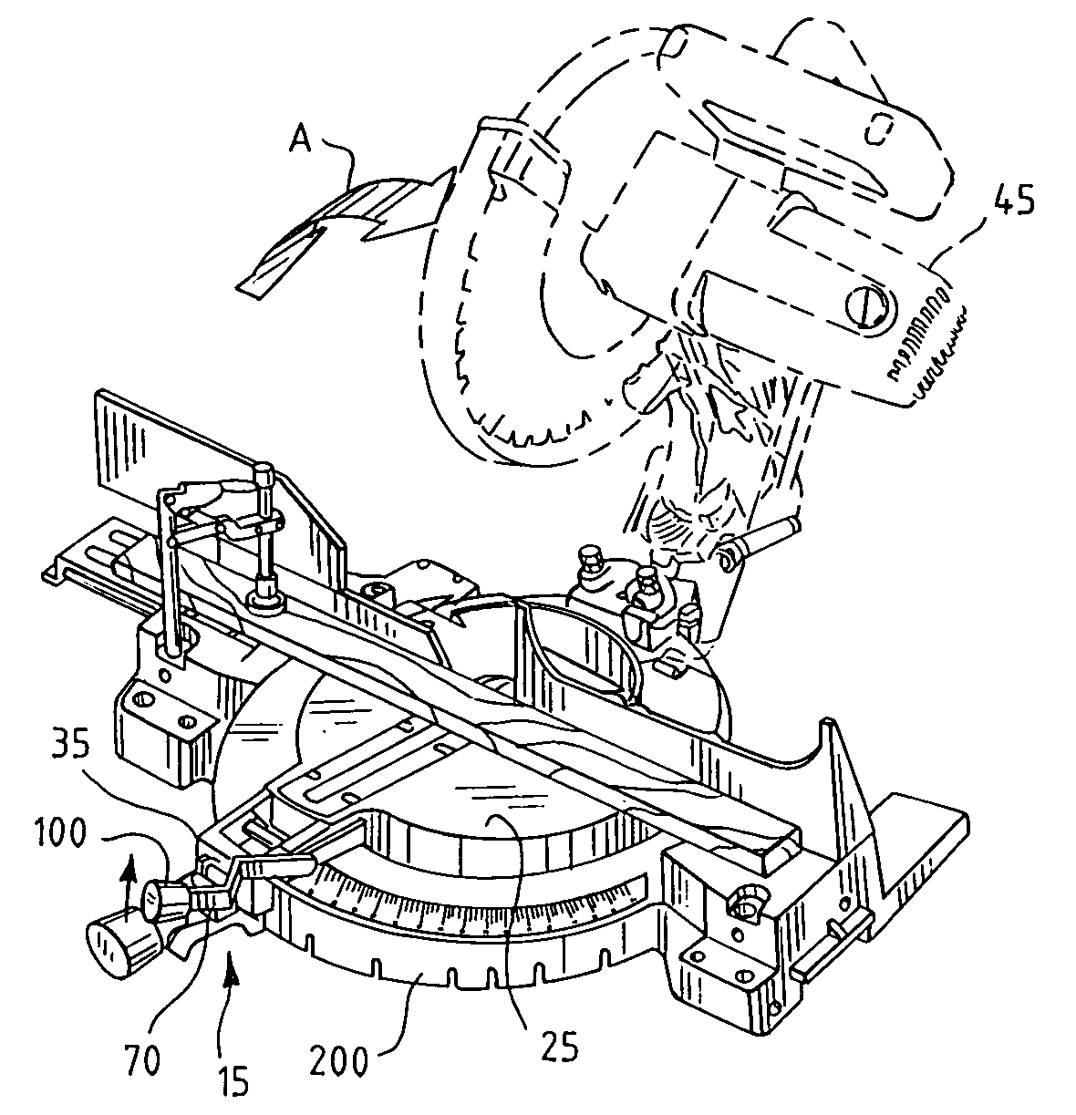
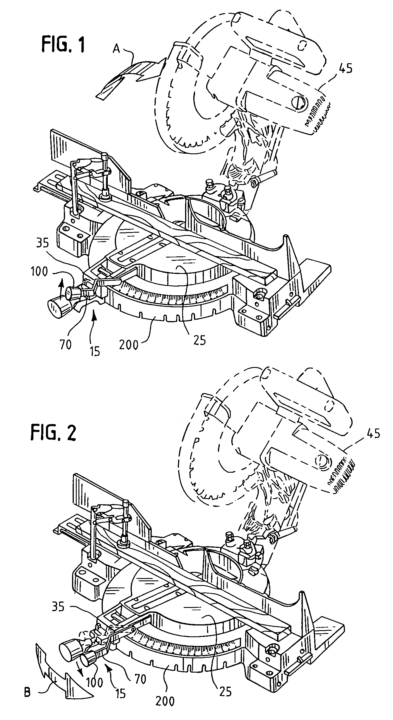
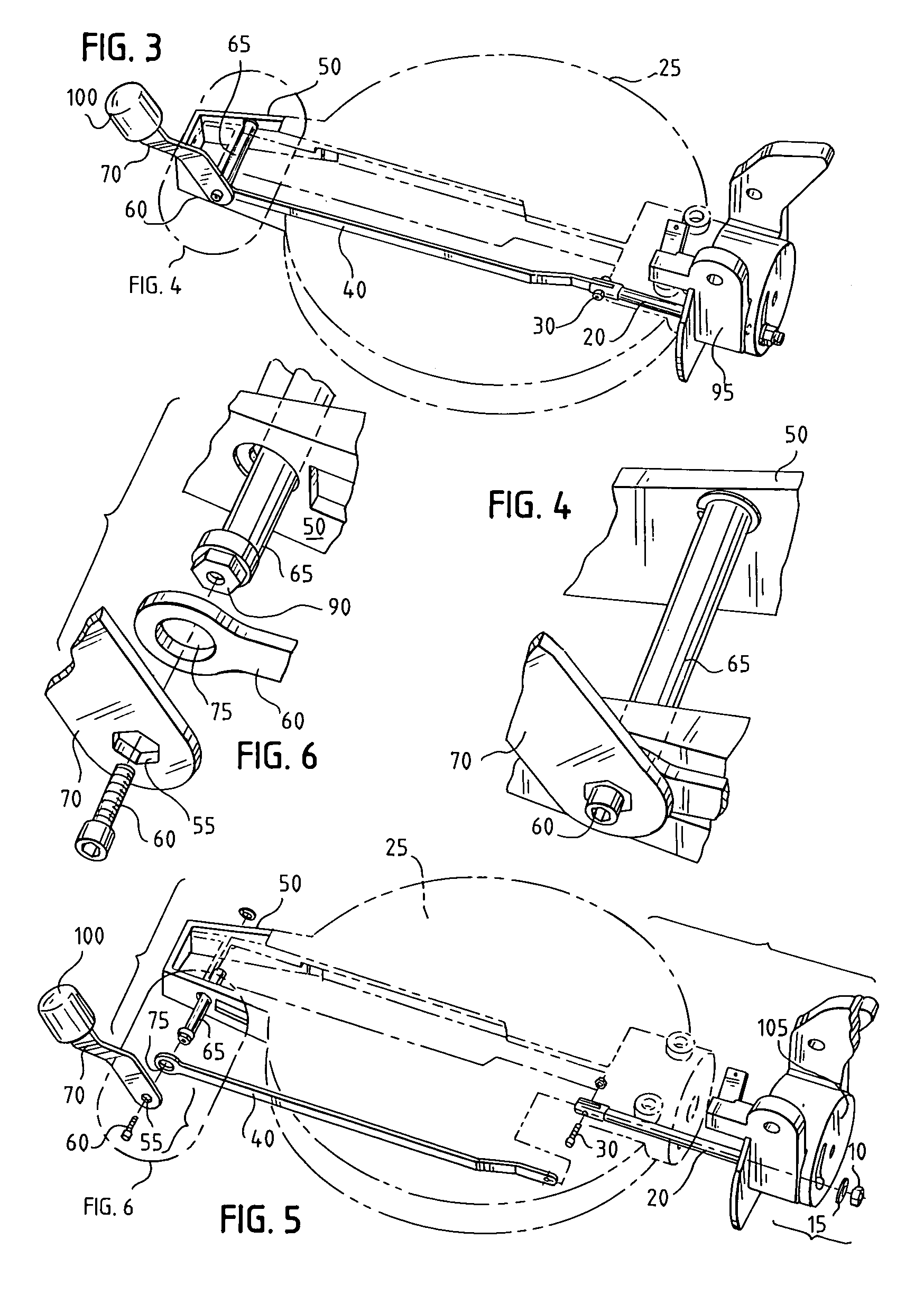
[0033]FIGS. 1–2 provide a general understanding of how a bevel locking system functions to hold a tilt or bevel angle for a power tool. In FIGS. 1–2, there is illustrated, in accordance with the present invention, a bevel locking system 15 for holding a power tool 45 at a selected bevel or tilt angle for making a bevel cut. The movement of the power tool 45 along the bevel or tilt angles is indicated by a curved arrow A in FIG. 1. When the bevel lock lever 70 is unlocked, as in the embodiment shown in FIG. 1, the power tool 45 is free to pivot in the direction indicated by the curved arrow A. When the bevel lock lever 70 is locked, as in the embodiment shown in FIG. 2, the power tool 45 is held steady at a selected bevel angle. In the embodiment shown in FIG. 2, the selected angle appears to be about 0°.
[0034]In embodiments of the present invention in which the front-accessible bevel locking system is incorporated into a miter saw, there is also provided a work surface 25 and suppor...
second embodiment
[0037]the present invention is shown in FIGS. 11–13. In the second embodiment shown in FIGS. 11A–B, the handle 100 is replaced with a bevel lock lever 70′, which functions as both a handle and a bevel lock lever in the second embodiment. As shown in FIGS. 11–13, in the second embodiment, the bevel locking system 15′ is mounted to the left side of the support arm 35. A user of the bevel locking system 15′ presses downwardly on the bevel lock lever 70′ to put the bevel locking system 15′ in the locked position.
[0038]The bevel locking system 15′ for the second embodiment differs from the bevel locking system 15 of the first embodiment in several important respects. The cam shaft follower 40 of the first embodiment is replaced instead with a cam follower 40′ (further described in connection with the link rod 20′ below). The interior of the cam follower 40′ has a D-like shape, which is most evident in the side view of the second embodiment shown in FIG. 13. In addition, there is no cam s...
PUM
| Property | Measurement | Unit |
|---|---|---|
| angle | aaaaa | aaaaa |
| acute angle | aaaaa | aaaaa |
| angle | aaaaa | aaaaa |
Abstract
Description
Claims
Application Information
 - R&D
- Intellectual Property
- Life Sciences
- Materials
- Tech Scout
- Unparalleled Data Quality
- Higher Quality Content
- 60% Fewer Hallucinations
Browse by: Latest US Patents, China's latest patents, Technical Efficacy Thesaurus, Application Domain, Technology Topic, Popular Technical Reports.
© 2025 PatSnap. All rights reserved.Legal|Privacy policy|Modern Slavery Act Transparency Statement|Sitemap|About US| Contact US: help@patsnap.com


