Compound spring-loaded archery bow

a spring-loaded, compound technology, applied in the direction of spring guns, white arms/cold weapons, weapons, etc., can solve the problems of bows that cannot be disassembled for compact storage, handling, transportation, etc., and achieve the effect of optimum performance, easy adjustment, and easy and accurate tuning of performance characteristics of bows

Inactive Publication Date: 2007-04-10
YORK MERINETH S
View PDF12 Cites 51 Cited by
  • Summary
  • Abstract
  • Description
  • Claims
  • Application Information

AI Technical Summary

Benefits of technology

[0004]The compound spring-loaded archery bow of the subject invention provides an improved compound spring-loaded archery bow to solve the problems of the prior art. The compound spring-loaded archery bow of the subject invention has improved independent upper and lower bowstring coil spring tensioning assemblies that permit the performance characteristics of the bow to be easily and accurately tuned for optimum performance. The nock point on a bowstring where the arrow is positioned when being shot from the bow is typically located off center (i.e. rather than having the nock point of the bowstring located equidistant from the upper and lower ends of the bowstring where the bowstring is attached to cam members of the bow, the nock point is located closer to one end of the bowstring than the other end of the bow string). With the nock point on the bowstring typically being located off center, the ability of the compound spring-loaded archery bow of the subject invention to be easily adjusted to independently adjust the poundage exerted on the upper and lower ends of the bowstring to place the bowstring in tension is even more important to enable the bow to be easily and accurately tuned for optimum performance. The use of the upper and lower independent coil spring tensioning assemblies of the compound spring-loaded archery bow of the subject invention further enhances the performance of the compound spring-loaded archery bow of the subject invention by enabling the poundage exerted on the bowstring by the independent coil spring tensioning assemblies to be easily and accurately set and once set at a desired poundage, by maintaining the poundage settings to ensure the continued optimum performance in service of the compound spring-loaded archery bow of the subject invention. In addition to the above, the coil spring tensioning assemblies of the compound spring-loaded archery bow of the subject invention are contained within the upper and lower limbs of the bow frame so that the compound spring-loaded archery bow of the subject invention retains the appearance of a traditional archery bow and in a preferred embodiment of the bow, the bow is easy to disassemble for compact storage, handling, and transport.
[0005]The compound spring-loaded archery bow of the subject invention includes a central riser with a handgrip and arrow rest and rigid upper and lower limbs. The upper limb extends upward from the central riser and the lower limb extends downward from the central riser to form a rigid bow frame with the configuration of a traditional archery bow. The rigid upper and lower limbs of the compound spring-loaded archery bow of the subject invention are hollow tubes that contain the coil spring tensioning assemblies for tensioning the bowstring. These coil spring tensioning assemblies are connected to top and bottom limb cam assemblies located, respectively, at the free top end portion of the upper limb and the free bottom end portion of the lower limb. The bowstring is also secured to and extends between the limb cam assemblies at the top and bottom of the compound spring-loaded archery bow. When the bowstring is drawn, the bow poundage coil springs of the coil spring tensioning assemblies contained within the upper and lower limbs are compressed placing the bowstring under increasing tension as the bowstring is drawn. When the archer releases the bowstring, the bow poundage coil springs of the coil spring tensioning assemblies in the upper and lower limbs rapidly expand and snap the bowstring rapidly back to its initial undrawn position to accurately propel an arrow from the bow.
[0006]With the structure of the coil spring tensioning assemblies of the subject invention and their location within the rigid upper and lower limbs of the rigid bow frame, when the bowstring of the compound spring-loaded archery bow of the subject invention is released by the archer, the kinetic energy developed by the coil springs of the upper and lower coil spring tensioning assemblies, as the coil springs of these assemblies rapidly expand, is released in the directions of the longitudinal axes of the rigid upper and lower limbs of the rigid bow frame. It is believed that this structure and this location of the coil spring tensioning assemblies of the subject invention causes the kinetic energy released by the upper and lower coil spring tensioning assemblies, initiated by the release of the bowstring when shooting an arrow, to cancel each other out and eliminate or substantially eliminate vibrations that would otherwise be set up in the bow to adversely affect the flight of the arrow as the arrow leaves the bow after the bowstring is released by the archer.

Problems solved by technology

While current traditional archery bows are frequently made of strong composite materials, the upper and lower resilient limbs of these bows sometimes fail and can cause serious injury.
The frames of these traditional archery bows have a unitary construction so that these bows cannot be disassembled for compact storage, handling, and transport.
This form of tensioning unit only permits the tension on the bowstring to be adjusted from the lower end of the bowstring and compromises the configuration of the bow so that the bow doesn't have the appearance of a traditional archery bow.

Method used


Image

  • Compound spring-loaded archery bow
  • Compound spring-loaded archery bow
  • Compound spring-loaded archery bow

Examples


Embodiment Construction

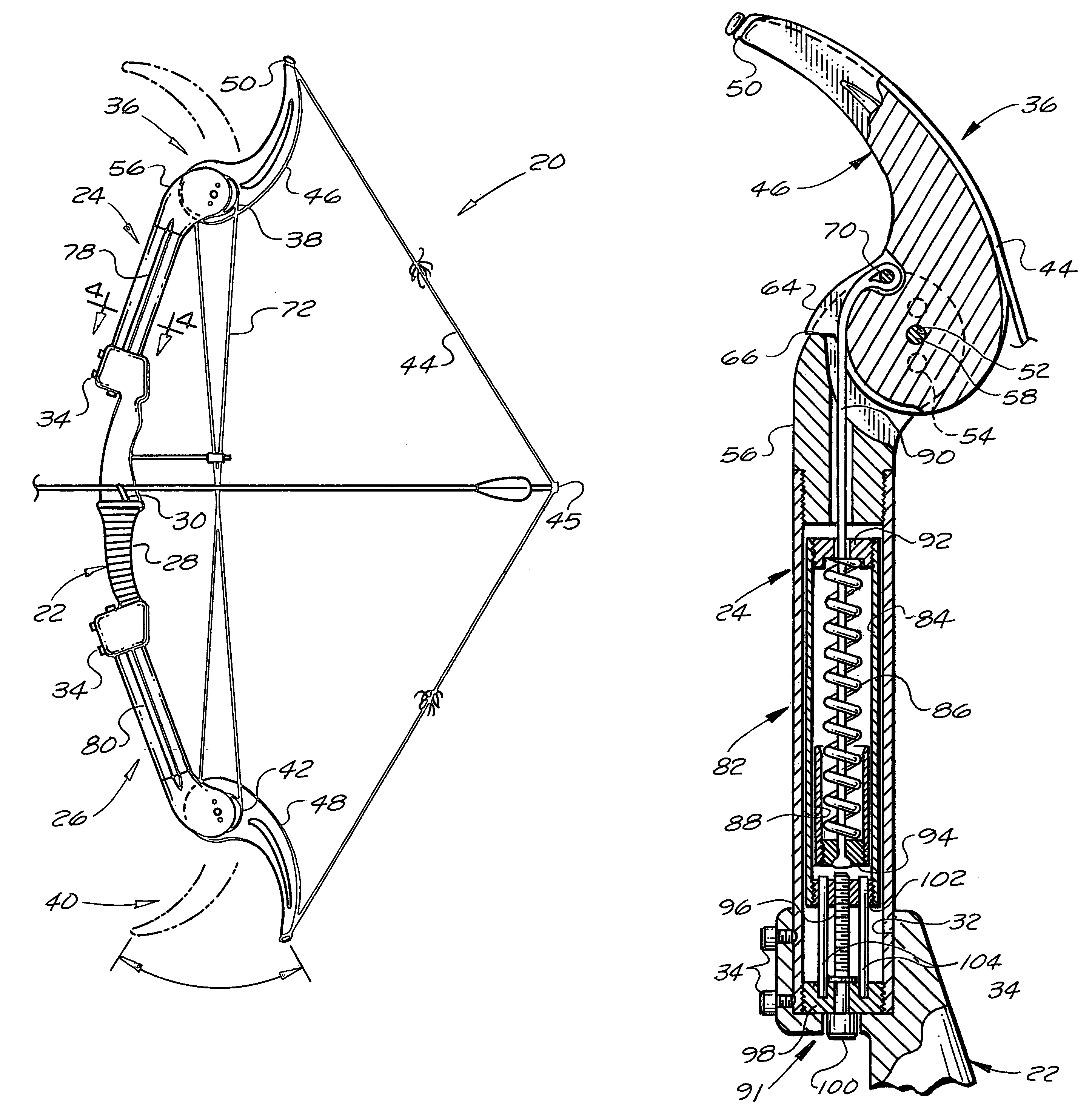
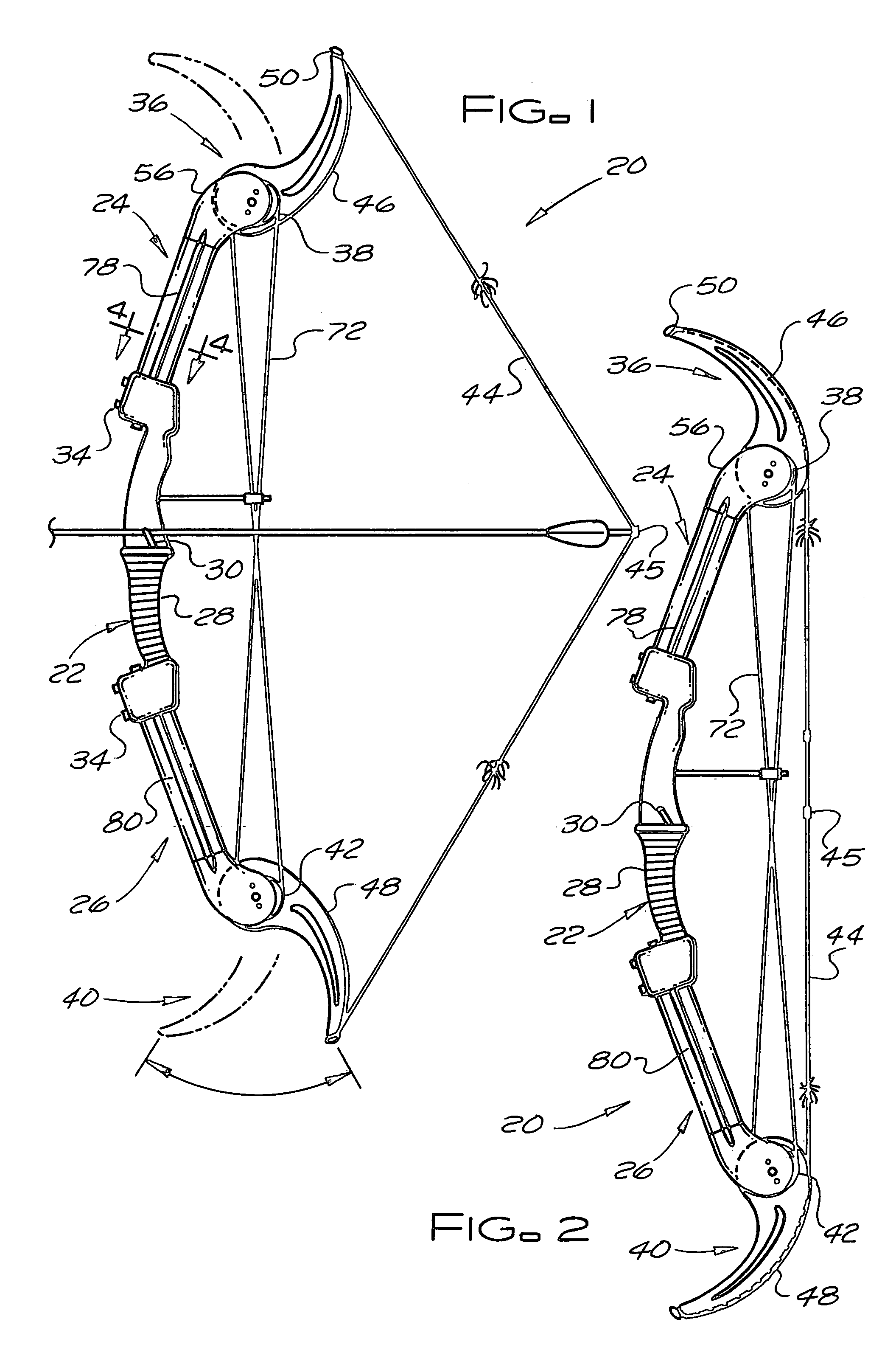
[0018]As shown in FIGS. 1 and 2, the compound spring-loaded archery bow 20 of the subject invention has a rigid bow frame that includes a rigid central riser 22, a rigid upper limb 24, and a rigid lower limb 26. The rigid central riser 22 had a handgrip 28 and an arrow rest 30. The rigid upper limb 24 extends upward from an upper end portion of the central riser 22, the rigid lower limb 26 extends downward from a lower end portion of the central riser 22, and the compound spring-loaded archery bow 20 has the appearance of a traditional archery bow.

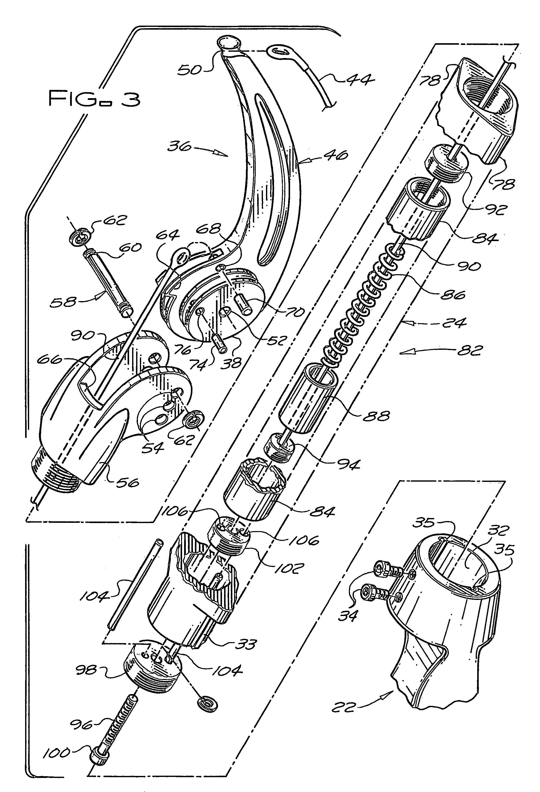
[0019]Preferably, the rigid upper limb 24 and the rigid lower limb 26 are detachably secured to the central riser 22 so that the compound spring-loaded archery bow 20 can be easily disassembled for compact storage, handling, and transport. In a preferred embodiment of the subject invention the upper end portion and the lower end portion of the rigid central riser 22 have sockets 32 for receiving the lower end portion of the rigid upper lim...


PUM


Abstract

A compound spring-loaded archery bow, which retains the appearance of a traditional bow, has a rigid bow frame that is formed by a central riser with a handgrip and arrow rest, an upper limb extending upward from the central riser and a lower limb extending downward from the central riser. Cam mechanisms are mounted at the upper end of the upper limb and the lower end of the lower limb and a bowstring is secured to and extends between the upper and lower cam mechanisms. When the bowstring is drawn from an initial preset position to shoot an arrow, there is a synchronized actuation of the upper and lower cam mechanisms. The upper and lower limbs are tubular and contain separate upper and lower spring assemblies for applying tension to the bowstring through the cam mechanisms only when the bowstring is drawn from its initial preset position. The degree of initial compression of the springs in the upper and lower spring assemblies can be independently adjusted to adjust the magnitude of the forces exerted on the bowstring by the assemblies when the bowstring is drawn to thereby set the maximum drawing force for the bowstring and the relative forces exerted on the bowstring by the assemblies.

Description

BACKGROUND OF THE INVENTION[0001]The subject invention relates to a compound spring-loaded archery bow and in particular to an improved compound spring-loaded archery bow with improved separate upper and lower spring tensioning assemblies and associated cam mechanisms for applying tension to the bowstring of the bow. The separate upper and lower spring tensioning assemblies are contained within the upper and lower rigid limbs of the bow so that the bow of the subject invention retains the appearance of a traditional archery bow while having the advantages of being a compound spring-loaded archery bow.[0002]A traditional archery bow has a central riser with a handgrip and arrow rest plus upper and lower resilient limbs that extend upward and downward from the central riser and provide the archery bow with its traditional appearance. The central riser and upper and lower resilient limbs of the archery bow form a leaf spring. A bowstring is attached to the free ends of the upper and lo...

Claims


Application Information

Patent Timeline
Patent Type & Authority Patents(United States)
IPC IPC(8): F41B5/00
CPCF41B5/0094F41B5/10
Inventor YORK, MERINETH S.
Owner YORK MERINETH S
Why Eureka
Try Eureka