Multilayer coil, winding method of same, and winding apparatus of same

a multi-layer coil and winding method technology, applied in the direction of capacitor manufacture, magnetic bodies, fixed capacitors, etc., can solve the problem of forcing the expansion of the outer diameter of the coil

Active Publication Date: 2007-04-10
NITTOKU ENG CO LTD
View PDF5 Cites 19 Cited by
  • Summary
  • Abstract
  • Description
  • Claims
  • Application Information

AI Technical Summary

Benefits of technology

[0008]The present invention has been made from the foregoing problems and has an object of providing a multilayer coil, a winding method of the multiplayer coil, and a winding apparatus of the multilayer coil, which in a case of winding a set of two or more wire rods in parallel and in line around a winding core having a cross section of a polygonal shape, prevents an increase of bulge in an outer direction of the winding core on a wire rod feeding face.

Problems solved by technology

This raises a problem that an outer diameter of a coil is forced to be increased.

Method used


Image

  • Multilayer coil, winding method of same, and winding apparatus of same
  • Multilayer coil, winding method of same, and winding apparatus of same
  • Multilayer coil, winding method of same, and winding apparatus of same

Examples


first preferred embodiment

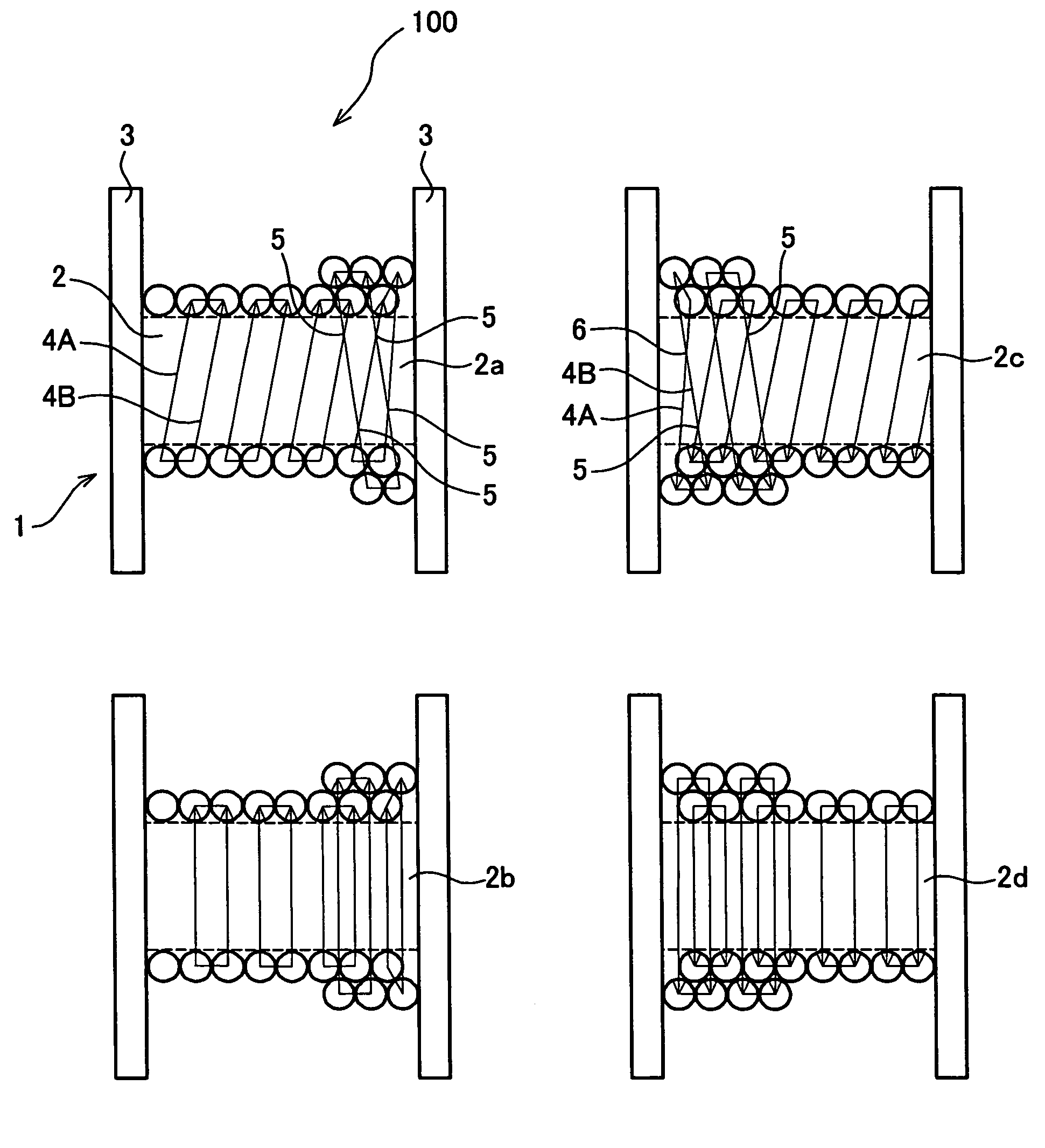
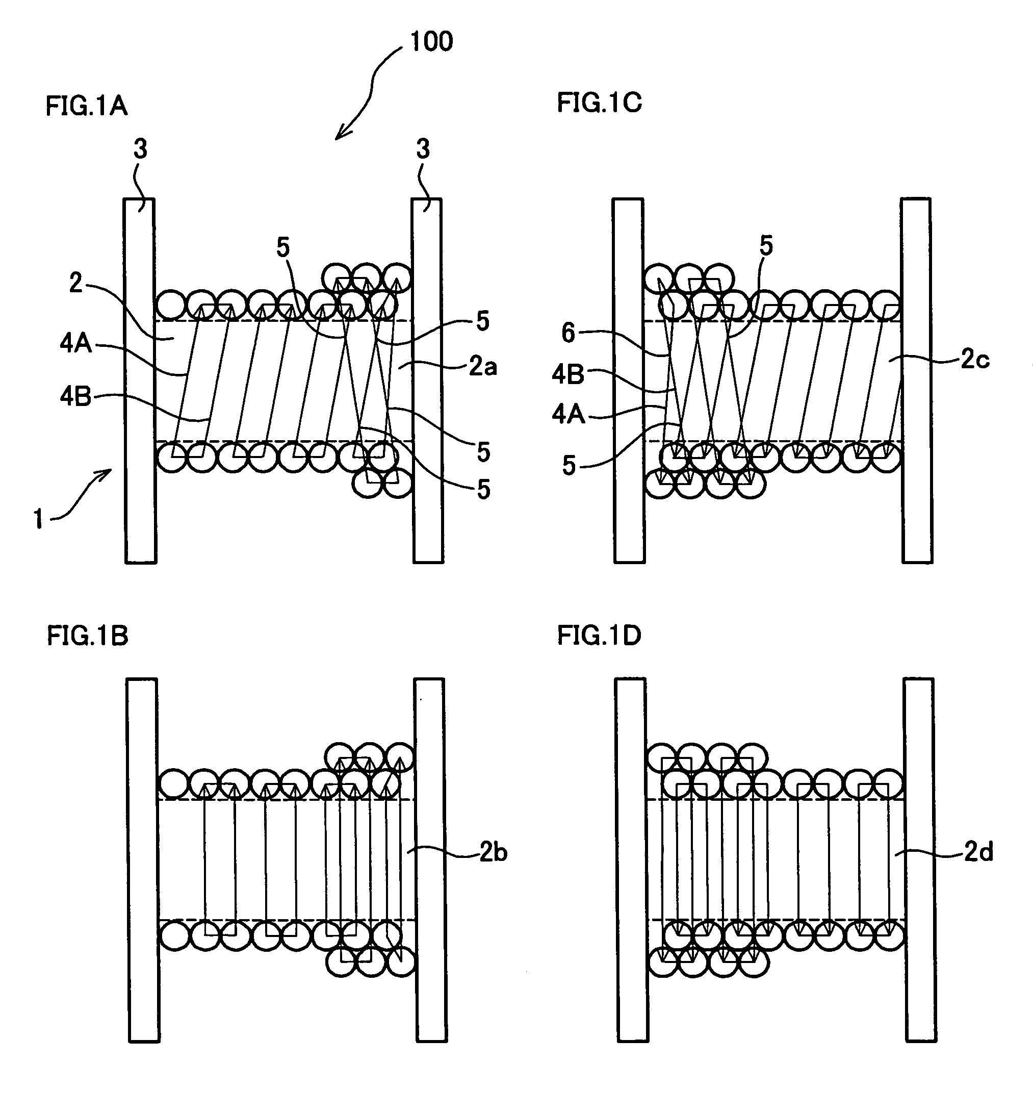
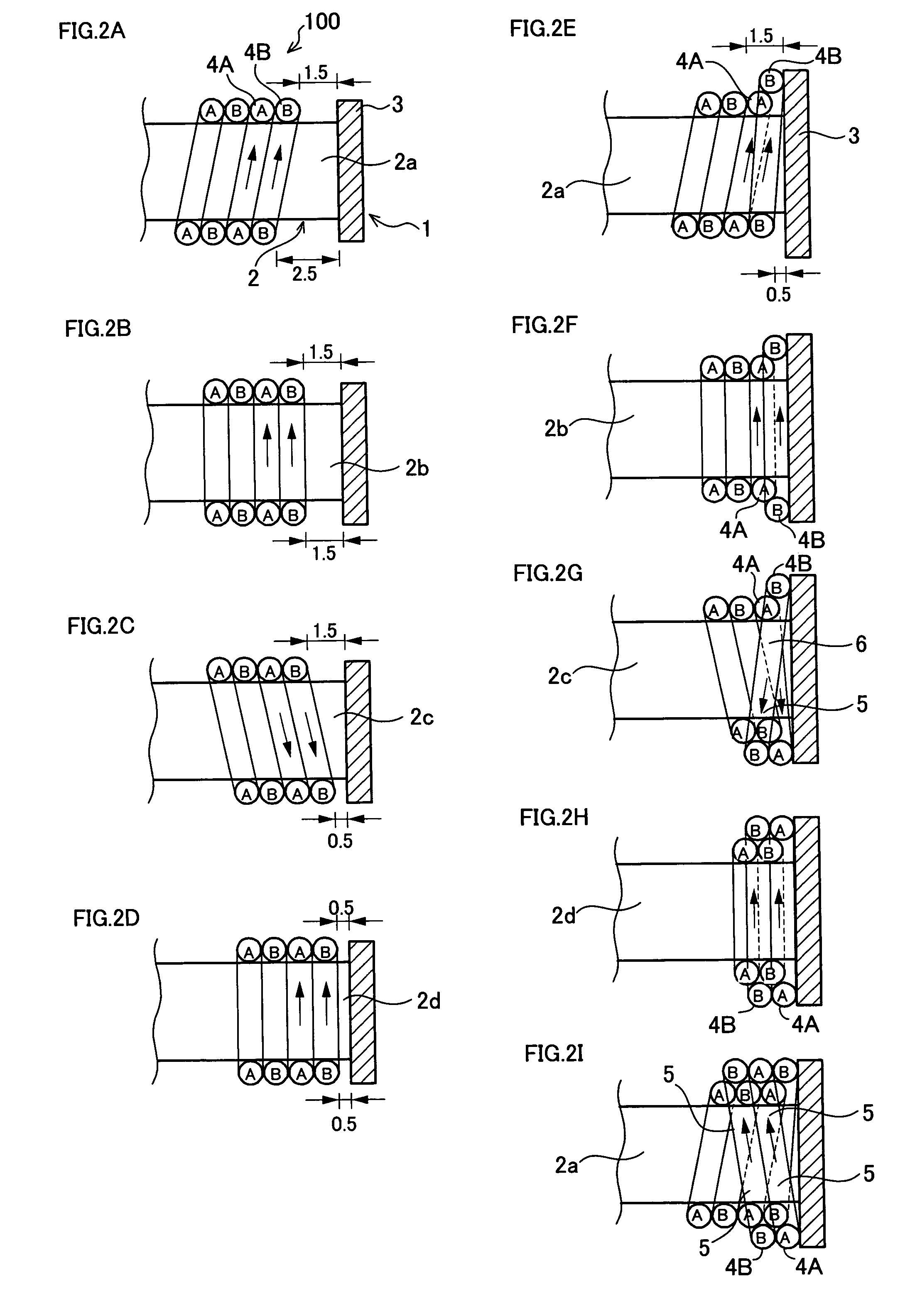
[0027]A multilayer coil 100 in a first preferred embodiment of the present invention will be explained with reference to FIGS. 1A–1D and FIGS. 2A–2I. FIGS. 1A–1D are views, each showing the multilayer coil 100 of which wire rods are wound around a winding core: FIG. 1A is a front view; FIG. 1B is a plan view; FIG. 1C is a rear view; and FIG. 1D is a bottom view. FIGS. 2A–2I are views, each showing a winding method at an end of a winding core of the multilayer coil 100. An arrow in the figures shows a winding direction. In FIGS. 2A–2I, only wire rods related to the explanation are illustrated and the other wire rods are not illustrated.

[0028]The multilayer coil 100 is constructed by winding wire rods around a bobbin 1 in multiple layers. The bobbin 1 is formed of a winding core 2 around which wire rods are wound and collars 3 disposed in both sides of the winding core 2, co-axial therewith. A cross section of the winding core is a square shape and a set of two wire rods 4A and 4B are...

second preferred embodiment

[0041]Next, a multilayer coil 200 in a second preferred embodiment of the present invention will be explained with reference to FIGS. 4A–4I, which show a winding method at an end of a winding core in the multilayer coil 200. FIGS. 4A, 4E and 4I are front views, FIGS. 4B and 4F are plan views, FIGS. 4C and 4G are rear views and FIGS. 4D and 4H are bottom views. Note that for explanatory convenience, the rear views as FIGS. 4C and 4G show a state where the bobbin 1 is seen transparently from the front side. In addition, only wire rods related to the explanation are illustrated and the other wire rods are not illustrated.

[0042]The multilayer coil 200 differs from the multilayer 100 in a point that the number of wire rods wound around the winding core 2 is three (4A, 4B and 4C). Wire rod feeding faces are three faces composed of a front face 2a, a plan face 2b and a back face 2c and an amount of the feeding is set as a wire diameter of one wire rod on each face. The feeding is not made ...

third preferred embodiment

[0055]Next, a multilayer coil 300 in a third preferred embodiment of the present invention will be explained with reference to FIGS. 5A–5I, which show a winding method at an end of a winding core in the multilayer coil 300. FIGS. 5A, 5E and 5I are front views, FIGS. 5B and 5F are plan views, FIGS. 5C and 5G are rear views and FIGS. 5D and 5H are bottom views. Note that for explanatory convenience, the rear views as FIGS. 5C and 5G show a state where the bobbin 1 is seen transparently from the front side. In addition, only wire rods related to the explanation are illustrated and the other wire rods are not illustrated.

[0056]The multilayer coil 300 differs from the multilayer coils 100 and 200 in a point that the number of wire rods wound around the winding core 2 is four (4A, 4B, 4C and 4D). Wire rod feeding faces are all faces (composed of a front face 2a, a plan face 2b, a back face 2c and a bottom face 2d) and an amount of the feeding is set as an amount of one wire rod on each fa...


PUM

PropertyMeasurementUnit
diameteraaaaaaaaaa
outer diameteraaaaaaaaaa
widthaaaaaaaaaa

Abstract

In a multilayer coil which winds “n” wire rods (4) (“n” is an integer number of two or more) in line around a winding core (2) having a cross section of a polygonal shape. An intersection portion (5) is formed on a face where feeding of the winding core is made by feeding the wire rods by an amount of “n” wire rods during a period when the wire rods (4) are wound by one round around the winding core (2), so that the wire rods in a lower layer and an upper layer intersect therein. A twist portion (6) is formed at an end of at least one face out of the faces where the feeding is made, wherein two wire rods out of “n” wire rods are twisted to replace an arrangement of the wire rods.

Description

FIELD OF THE INVENTION[0001]The present invention relates to a multilayer coil and a winding method of the multilayer coil, and a winding apparatus of the multilayer coil.BACKGROUND OF THE INVENTION[0002]In a case of winding one wire rod in line around a bobbin as a tool for winding, for example, a bobbin a winding core of which has a cross section of a square shape, it is general to perform feeding equal to an amount of a wire diameter of a wire rod on one face of the four faces. In this case the feeding is not made in the other three faces.[0003]When a wire rod is wound to an end of the winding core and then moves on an upper layer for the winding thereon, since on the face where the feeding of the wire rod is made, the winding direction of the wire rod in the lower layer is in reverse to that in the upper layer, a hatched portion, as shown in FIG. 13, is an intersection portion where the wire rod in the lower layer intersects the wire rod in the upper layer. On the face (referred...

Claims


Application Information

Patent Timeline
Patent Type & Authority Patents(United States)
IPC IPC(8): B21F3/04
CPCH01F27/2823H01F41/0641H01F41/0625Y10T29/49071H01F41/069H01F41/086B42D9/007
Inventor HIGETA, YUJI
Owner NITTOKU ENG CO LTD
Why Eureka
Try Eureka