Image reading apparatus

a reading apparatus and image technology, applied in the direction of electrographic process apparatus, instruments, printers, etc., can solve the problems of delayed reading timing, defective read image, and difficulty in scanning by two image readings, and achieve the effect of small apparatus

Inactive Publication Date: 2007-04-10
CANON KK
View PDF21 Cites 41 Cited by
  • Summary
  • Abstract
  • Description
  • Claims
  • Application Information

AI Technical Summary

Benefits of technology

[0007]The present invention has been made in view of the above-noted points and has as its object to provide an image reading apparatus for reading two-side images at a time, for example, by both of an image sensor provided on a pressure plate side and a reduction optical system reading device provided on the main body side of the apparatus, and preventing the stray light of two light sources to thereby prevent the reading performance and the operability of jam removing from being spoiled.
[0019]As described above, according to the present invention, in an apparatus for reading the back side and front side of an original by two image reading means, images can be read without being affected by the stray light of respective light sources.
[0021]Also, by constructing the two original reading means so as to be parallel to each other, the feeding of the original in the sub-scanning direction can be made the same for the two reading means and therefore, the apparatus can be made small as compared with a system in which the sub-scanning direction is not the same direction.

Problems solved by technology

The apparatus of Japanese Patent Application Laid-Open No. 11-69086 does not have means for effecting the detection of the position of the original when the original is conveyed to image reading means and therefore, it is difficult to start the scanning by the two image reading means in conformity with the arrival position of the leading edge of the original.
Therefore, the read image may become a defective image having a blank space which is not the image of the original on the leading edge or the trailing edge thereof, or delayed in reading timing.
Also, in the apparatus of Japanese Patent No. 2928449, the image reading means opposed to each other are proximate to each other and therefore, lights from respective light sources may enter sensors on opposite sides and cause the read image to deteriorate.

Method used


Image

  • Image reading apparatus
  • Image reading apparatus
  • Image reading apparatus

Examples


first embodiment

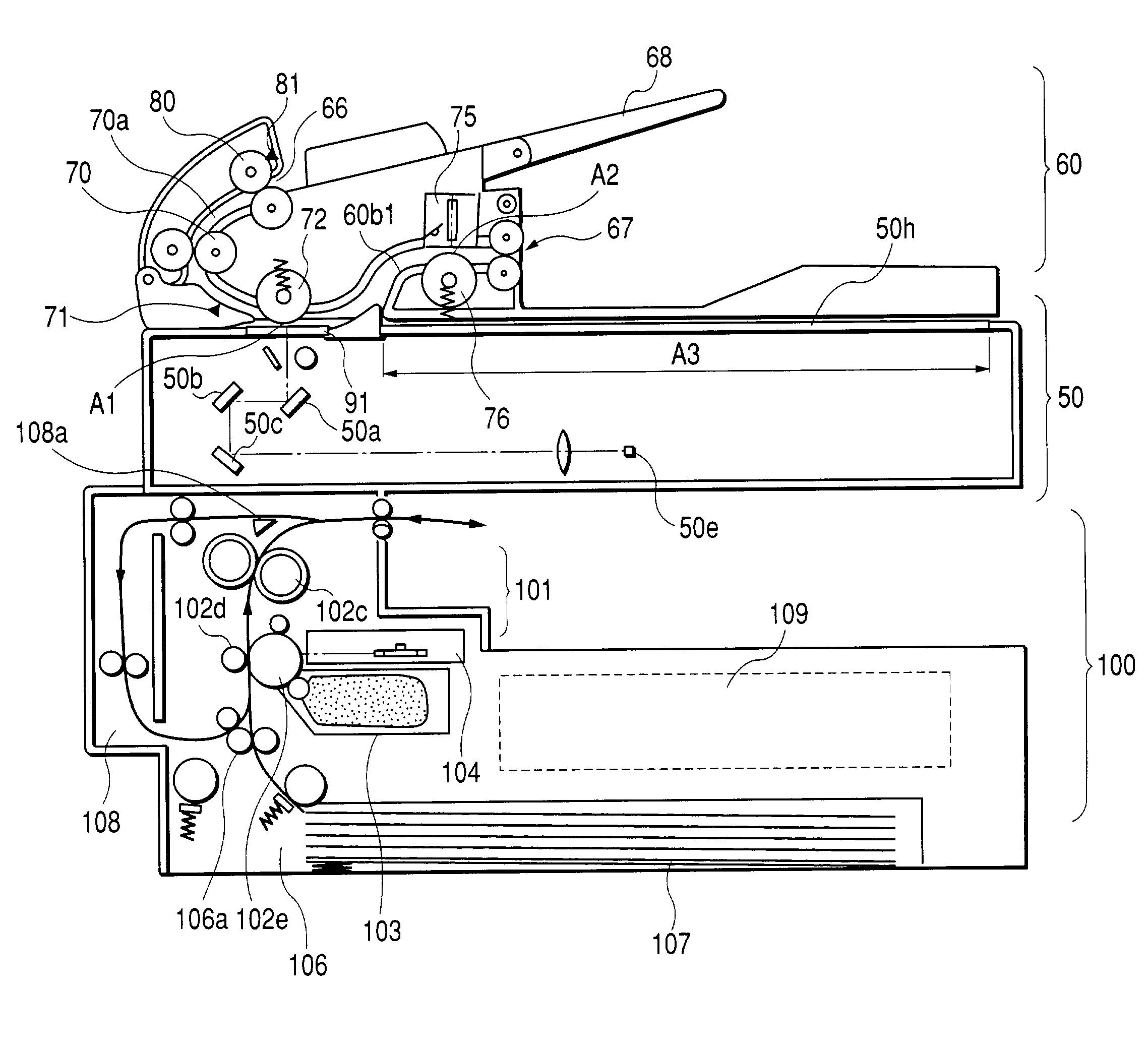
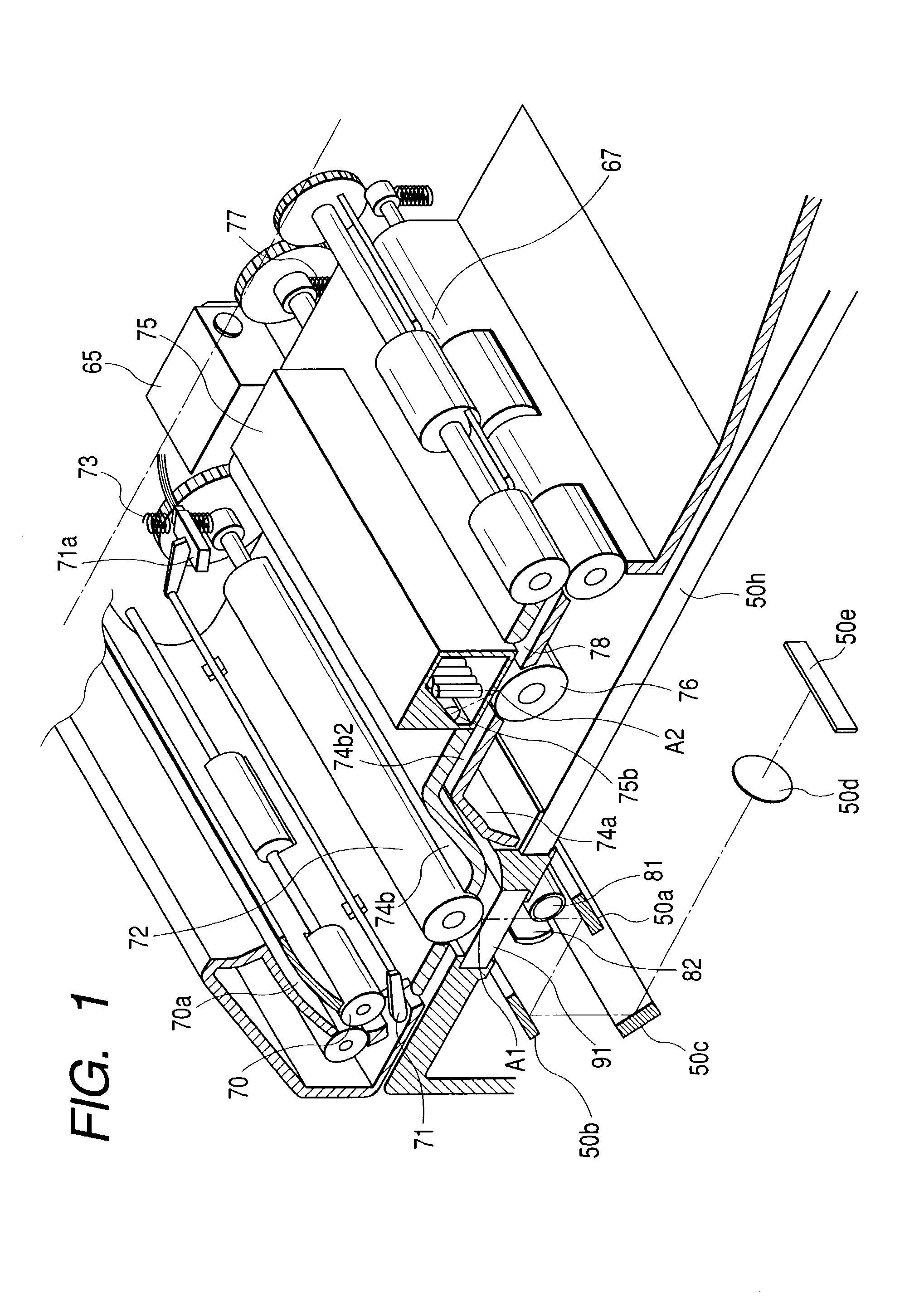
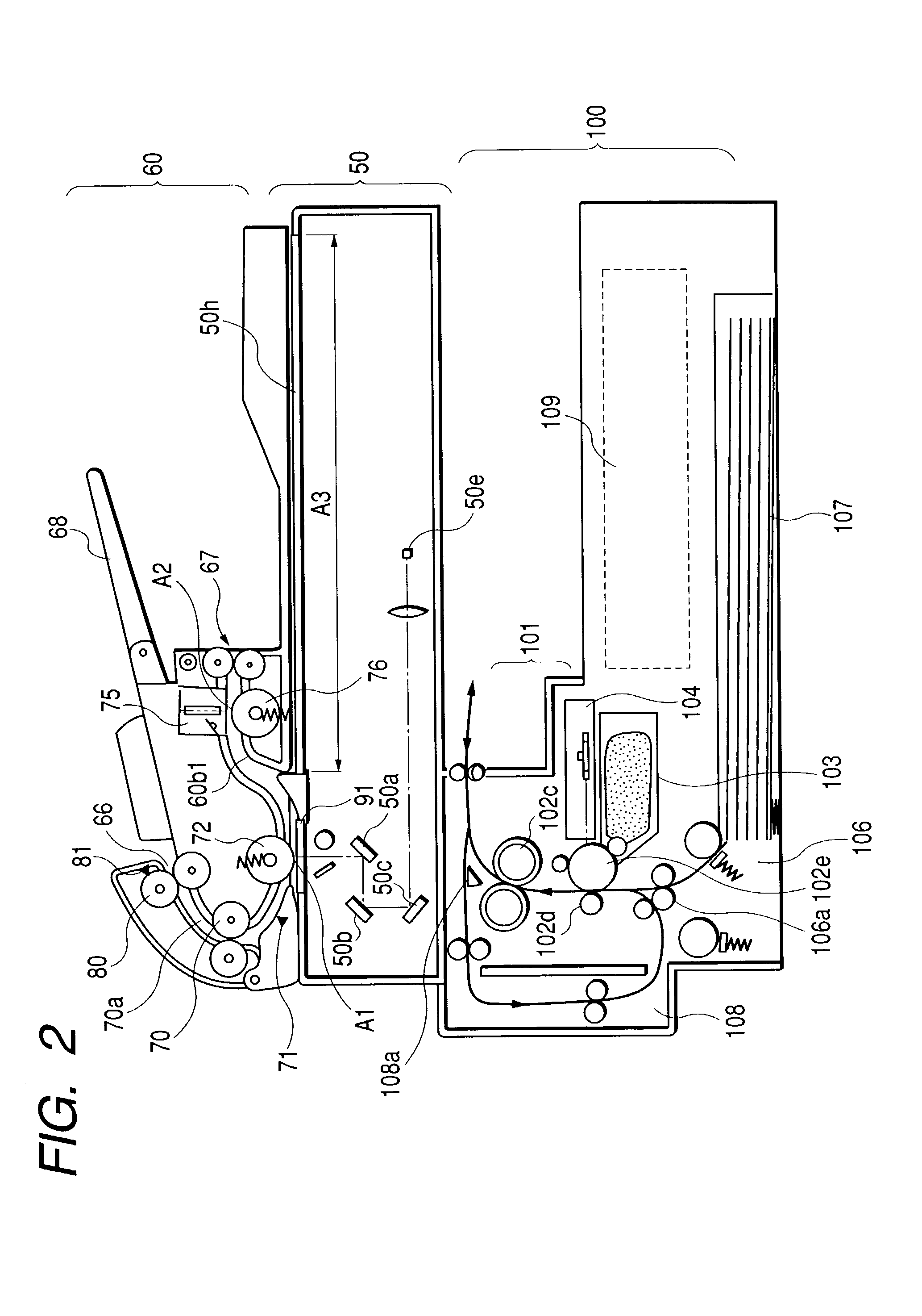
[0032]FIGS. 1 to 3 show a copying apparatus provided with the original reading apparatus of the present invention.

[0033]The apparatus of the present embodiment is provided with a so-called “book scanner portion” for placing a book original on an original glass stand 50h and moving an optical system to thereby effect sub-scanning and read the surface of the original, and a so-called “sheet scanner portion” provided with an original feeding device having a sheet separating mechanism above the original glass stand, and for effecting sub-scanning and reading (flow reading) the original while feeding a sheet original. Accordingly, as compared with such a case as seen in the conventional copying apparatus wherein an original is fed to a predetermined position, and thereafter is brought to a standstill and scanned, the scanning mechanism can be simplified and the reading time can be shortened.

[0034]The book scanner portion 50 is integral with the main body of the apparatus, and is provided...


PUM


Abstract

In an image reading apparatus having a first original reading device for reading one side of an original guided and fed by a guide, and a second original reading device disposed downstream of the first original reading device for reading the other side of the original, the guide is bent between the first original reading device and the second original reading device so as to shield the respective reading devices. The bending of the guide is done by bending an original feeding path so that direct rays and diffraction rays from each of two light sources may not enter respective photoelectric transfer elements associated with other light source, to thereby shield the photoelectric transfer elements from light of a light source not associated therewith.

Description

BACKGROUND OF THE INVENTION[0001]1. Field of the Invention[0002]The invention relates to an image reading apparatus, and a copying machine and a compound machine provided with the same.[0003]2. Description of Related Art[0004]When two-side images on an original are to be read at a time, the two sides are scanned at a time by image reading sensors having photoelectric transferring means disposed on the front side and back side, respectively, of the original, but in Japanese Patent Application Laid-Open No. 11-69086, there is proposed an apparatus for reading the two sides of an original substantially at a time. Also, in Japanese Patent No. 2928449, there is proposed an apparatus provided with two CCD reduction optical system reading means on the opposite sides of an original feed path and for reading the two sides of a moving original substantially at a time.[0005]The apparatus of Japanese Patent Application Laid-Open No. 11-69086 does not have means for effecting the detection of th...

Claims


Application Information

Patent Timeline
Patent Type & Authority Patents(United States)
IPC IPC(8): H04N1/04H04N1/00H04N1/203
CPCH04N1/203H04N1/2032H04N1/2034
Inventor YOKOTA, MASAHIKOISHIZUKA, HARUOYOSHIDA, TSUYOSHI
Owner CANON KK
Why Eureka
Try Eureka