Disk drive support assembly, clamp assembly and disk drive carrier

a technology for clamping and disk drives, applied in the direction of instruments, casings/cabinets/drawers, casings/cabinets/drawers, etc., can solve the problems that other similar known arrangements do not lend themselves to automated loading and unloading of disk drives using robots or other automated machinery, and other similar arrangements do not lend themselves to automation. , to achieve the effect of facilitating the automation of the loading and unloading process and reducing the clamping load

Active Publication Date: 2007-04-10
XYRATEX TECH LTD
View PDF11 Cites 66 Cited by
  • Summary
  • Abstract
  • Description
  • Claims
  • Application Information

AI Technical Summary

Benefits of technology

[0008]By using a discrete, removable disk drive carrier instead of clamping the disk drive directly to the relatively massive block, automation of the loading and unloading of disk drives onto the block is facilitated. Automation avoids the slow and laborious manual loading and unloading of the prior art. The disk drive and disk drive carrier are clamped together to the block. The servo writing may be for example of the self-servo writing type in which all servo tracks are written by the product head whilst the disk drive is clamped to the block, or may be of the servo fill type where only some of the servo tracks are written by the product head whilst the disk drive is clamped to the block.
[0043]The disk drive carrier preferably comprises a biasing and laterally compliant arrangement for biasing a removable disk drive card received in the first region into engagement with a disk drive carried by the carrier. This biasing with lateral compliance helps to improve the connection and also allows for some tolerance variations that arise during manufacture. The biasing and laterally compliant arrangement is preferably removable from the carrier. The biasing and laterally compliant arrangement may be mounted on a tray which is removable from the disk drive carrier.

Problems solved by technology

However, this and the other similar known arrangements do not lend themselves to automated loading and unloading of disk drives using robots or other automated machinery.
However, in the first of these prior art arrangements, clamping and unclamping of the disk drive is in essence a manual operation, and the arrangement again does not lend itself too automation.

Method used


Image

  • Disk drive support assembly, clamp assembly and disk drive carrier
  • Disk drive support assembly, clamp assembly and disk drive carrier
  • Disk drive support assembly, clamp assembly and disk drive carrier

Examples


Embodiment Construction

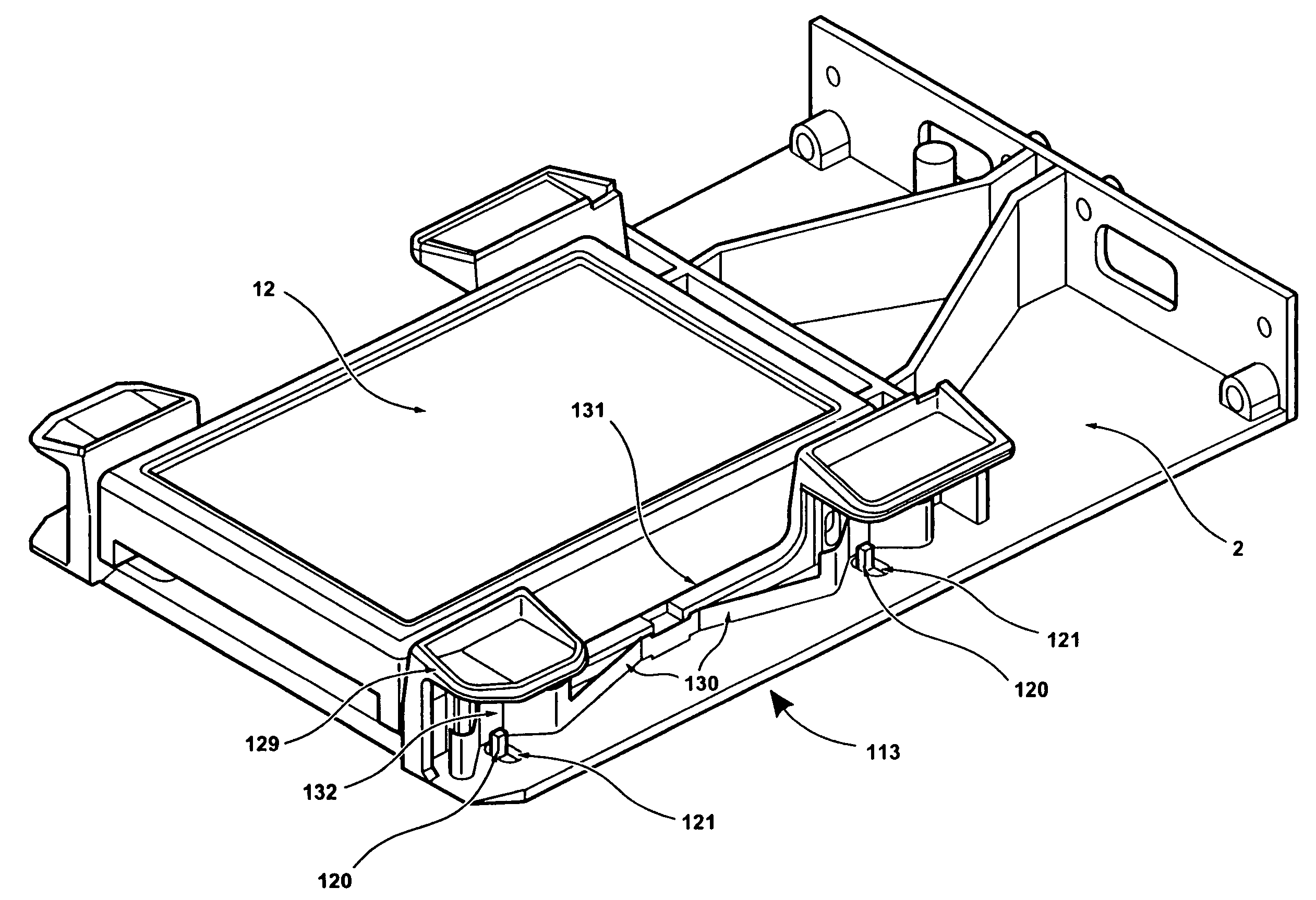
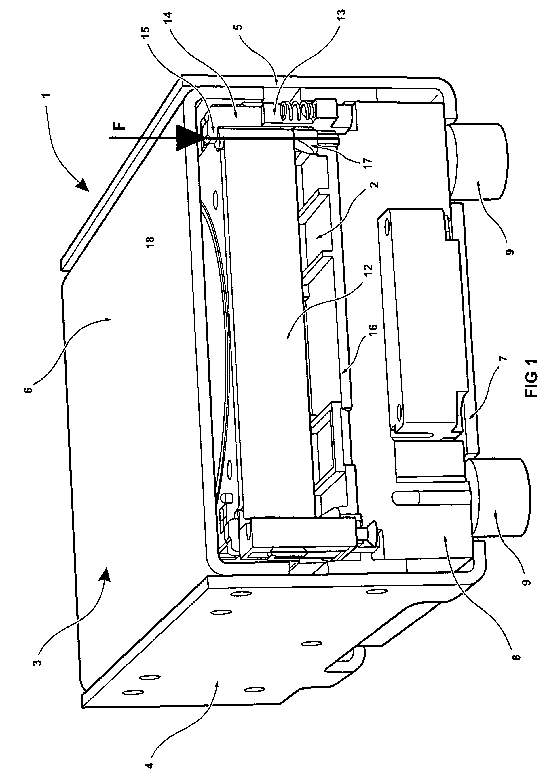
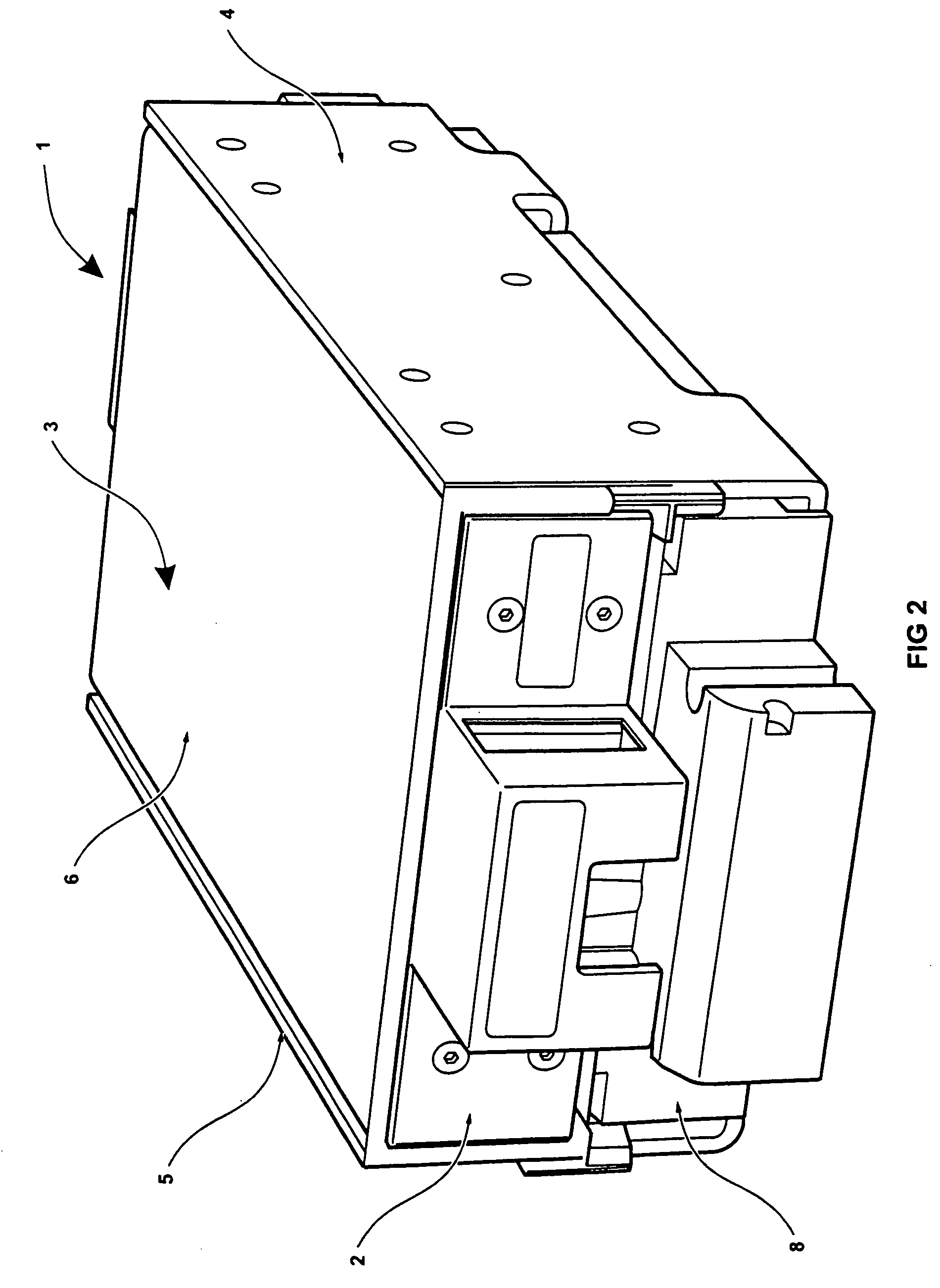
[0067]Referring initially to FIGS. 1 to 4, there is shown a disk drive support assembly 1 having a disk drive carrier 2 removably mounted therein. The assembly 1 has a housing or “cage”3 which has two opposed sides 4,5, a lid 6 and a base 7. Mounted internally in the lower part of the cage 3 is a relatively massive block 8, which may be made of a high density material, such as steel or granite for example. The disk drive carrier 2 is received internally in the upper part of the cage 3.

[0068]The relatively massive block 8 is mounted on vibration-damping mounts 9 which pass through corresponding apertures (not shown) in the base 7 of the cage 3. The vibration-mounting mounts 9 are preferably made of an elastomeric material, such as Sorbothane (trade mark), which is preferably under some 20% compression. As will be discussed further below, the cage 3 may be mounted in a cell in a rack of plural cells. The mounting is such that the vibration-damping mounts 9 sit on the floor of the cell...


PUM

PropertyMeasurementUnit
diameteraaaaaaaaaa
frequencyaaaaaaaaaa
movementaaaaaaaaaa

Abstract

A disk drive support assembly has a clamp arrangement for releasably clamping a disk drive to a massive block. The clamp arrangement may be an inflatable actuator that is operable to clamp the disk drive to the block via a disk drive carrier. Various clamp assemblies for clamping a disk drive to a substrate, such as a disk drive carrier, are also disclosed. A disk drive carrier that can be adapted for use with different types of disk drive is also disclosed. Such disk drives include those that provide for electrical and / or data connections under the disk drive, those that provide for electrical and / or data connections at the rear of the disk drive, and those that have their own so-called product card associated therewith.

Description

[0001]The present invention claims priority from U.S. Ser. No. 60 / 478,467 filed Jun. 16, 2003, the entire content of which is incorporated herein in its entirety.FIELD OF THE INVENTION [0002]The present invention relates to a disk drive support assembly, a clamp assembly, and a disk drive carrier.DESCRIPTION OF RELATED ART [0003]There are a number of applications when it is necessary to mount a disk drive in some other apparatus. These include for example when the disk drive is tested during manufacture and when the disk drive is in use for data storage applications or the like. A particular application is when servo tracks are written to the disk drive during the manufacturing process. Servo tracks are used during normal use of the disk drive to enable the read / write head (also known as the product head) of the disk drive to know its location over the disk(s). Two particular emergent technologies for writing servo tracks are the self-servo writing process and the self-servo fill pr...

Claims


Application Information

Patent Timeline
Patent Type & Authority Patents(United States)
IPC IPC(8): G06F1/16G11B5/012G06F1/18G11B5/596
CPCG06F1/184G06F1/187G11B5/59633
Inventor KAY, ALEXANDER S.MUNCASTER, TIMOTHY J.NINEHAM, ANDREW J.ATKINS, ANDREW W.
Owner XYRATEX TECH LTD
Why Eureka
Try Eureka