Freezable fluid cell for cryo-electron microscopy

a fluid cell and cryo-electron technology, applied in the field of cryo-electron microscopy, can solve the problems of inconsistent background noise signals across the sample, blotting methods for creating thin samples, and vitrified biological samples which were often poorly controlled

Active Publication Date: 2022-08-02
BRANDEIS UNIV
View PDF19 Cites 0 Cited by
  • Summary
  • Abstract
  • Description
  • Claims
  • Application Information

AI Technical Summary

Benefits of technology

[0009]The present disclosure also facilitates the automation process. Previous methods hindered automation for high-resolution cryo-EM imaging because traditional blotting and plunge freezing systems create ice thickness that varies across the substrate surface. This necessitates manual intervention to find areas that are sufficiently thin to obtain high-resolution information, yet not so thin that proteins are excluded from the ice. For example, thick ice diminishes signal, but if ice is too thin proteins will be pushed away. The present disclosure facilitates automation because it creates ice of customized and uniform ice thickness that also accommodates the proteins. As a consequence, a computer controlled imaging system can move from point to point acquiring images and the images will be of consistent quality because the ice thickness is constant. Further, the present disclosure also facilitates the automation process through a regular array of imaging windows.
[0010]According to one aspect, the present disclosure provides a freezable fluid cell system for cryo-electron microscopy. The freezable fluid cell system comprises a top chip and a bottom chip. The top chip includes a first structural member joined to a first electron transparent member. The bottom chip includes a second structural member joined to a second electron transparent member. The freezable fluid cell also includes a spacer positioned between the top chip and the bottom chip in which the spacer joins the top chip and the bottom chip to define one or more channels between the first electron transparent member and the second electron transparent member. The top chip further includes one or more inlet ports and outlet ports that extend through the first structural member and the first electron transparent member such that the inlet port, the outlet port, and the channel are in fluid communication. The inlet port and the exit port allow the freezable fluid cell device to be used and reused without disassembly of the device.
[0011]Suitable materials for the first and second electron transparent members may include silica, silicon nitride, silicon carbide, graphene, or derivatives thereof that are deposited onto the respective first or second structural member. It is contemplated that use of graphene or silicon carbide may improve the image resolution by reducing the noise present in the system.
[0014]In some forms, the spacer may comprise silicon oxide, indium, or microparticle beads and may have a thickness of 2 μm or less. In some non-limiting examples, the thickness of the spacer 108 for cell biology applications may benefit from having the thickness of the spacer be around 1 μm, while high-resolution protein imaging benefits from the thickness of the spacer 108 being around 20 nm. In some configurations, the thickness of the spacer 108 may be between 20 nm and 1 μm. In a preferred configuration, thickness of the spacer 108 may be between 20 and 200 nm. In the case of indium, the thermal and electrical conductivity of indium may facilitate charge dissipation during imaging.

Problems solved by technology

Previous approaches for imaging cryo-EM samples used robotic blotting methods for creating thin, vitrified biological samples which were often poorly controlled.
These previous blotting methods resulted in frozen samples with variable ice thicknesses due to large air-liquid interfaces, and concentration gradients of the macromolecule assemblies.
Furthermore, the variable ice thickness associated with previous blotting methods results in inconsistent background noise signals across the sample.
Inconsistent background noise signals complicates data post processing and image reconstruction.
This sample preparation stage of cryo-EM is widely considered the bottleneck in structure determination and an obstacle to automation of structure determination.
The present disclosure also removes the air-liquid interface that has been largely unavoidable using robotic blotting methods, which can be problematic in three-dimensional structure determination.
Previous methods hindered automation for high-resolution cryo-EM imaging because traditional blotting and plunge freezing systems create ice thickness that varies across the substrate surface.

Method used


Image

  • Freezable fluid cell for cryo-electron microscopy
  • Freezable fluid cell for cryo-electron microscopy
  • Freezable fluid cell for cryo-electron microscopy

Examples


Embodiment Construction

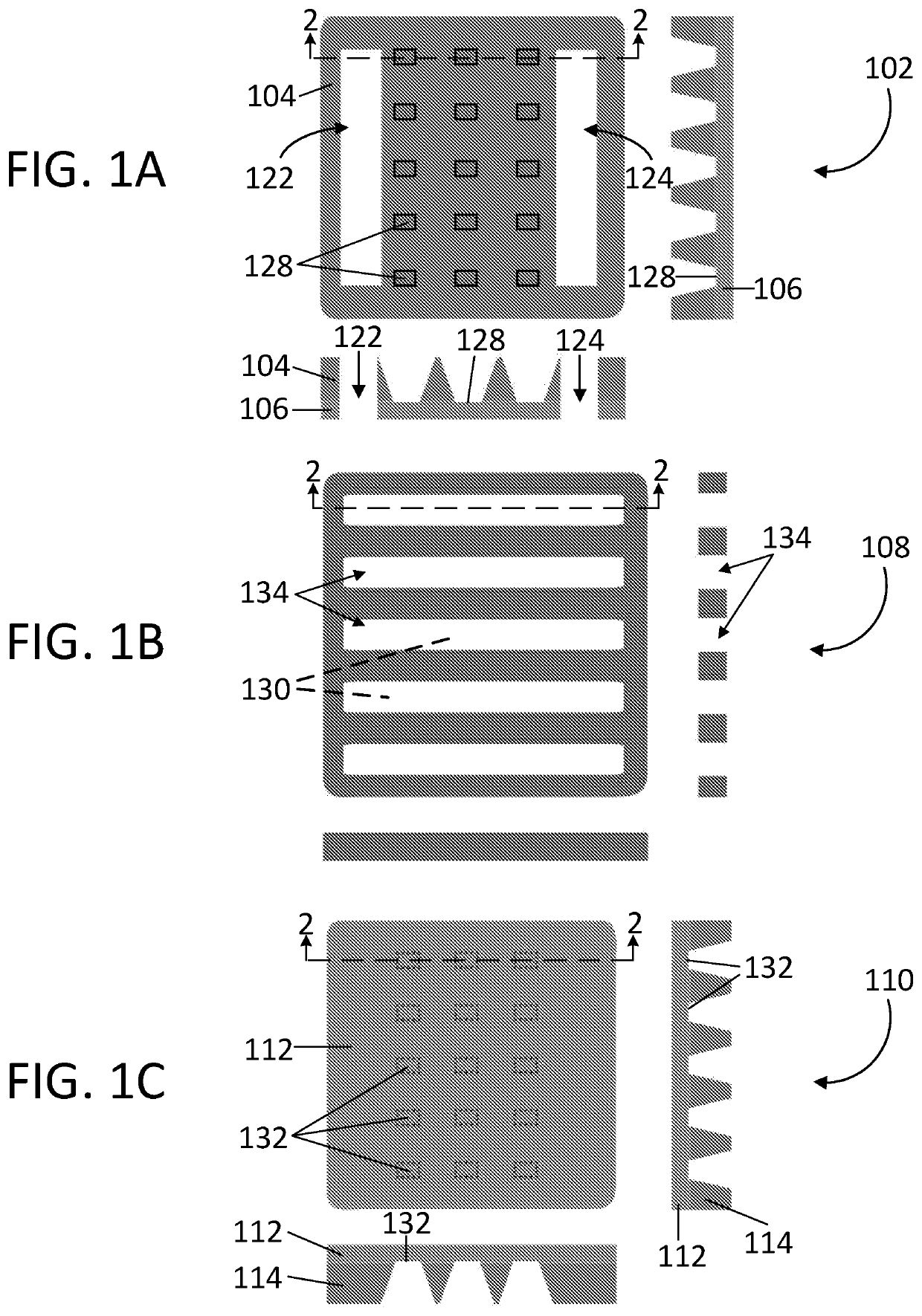
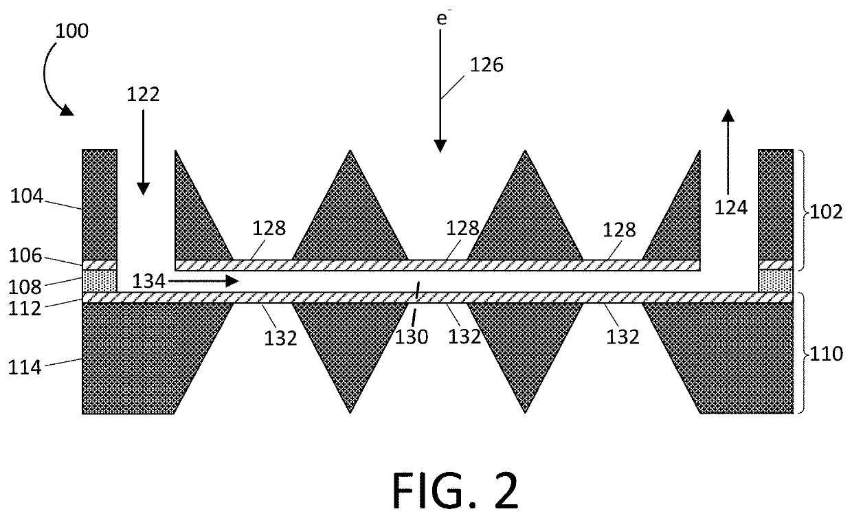
[0034]Referring first to FIGS. 1A, 1B, 1C, and 2, one exemplary embodiment of a freezable fluid cell system 100 according to the present disclosure is shown. The freezable fluid cell system 100 comprises a top chip 102, a spacer 108, and a bottom chip 110. In each of FIGS. 1A, 1B, and 1C, a top view along with a respective pair of cross sectional side views for each section (top, bottom, spacer) of the freezable fluid cell system 100 is illustrated.

[0035]In FIG. 1A, the top chip 102 of a freezable fluid cell system 100 is shown. The top chip 102 includes a first structural member 104 joined to a first electron transparent member 106. The top chip 102 has at least one inlet port 122 and at least one exit port 124 that extends through the first structural member 104 and the first electron transparent member 106 such that at least one channel 134 within the spacer 108 (described in more detail below and show in FIGS. 1B and 2) can remain in fluid communication with the inlet port 122 a...


PUM

PropertyMeasurementUnit
thicknessaaaaaaaaaa
thicknessaaaaaaaaaa
thicknessaaaaaaaaaa

Abstract

A system and method for imaging a biological sample using a freezable fluid cell system is disclosed. The freezable fluid cell comprises a top chip, a bottom chip, and a spacer to control the thickness of a vitrified biological sample. The spacer is positioned between the top chip and the bottom chip to define a channel that is in fluid communication with an inlet port and an exit port to the freezable fluid cell system. The channel can be filled with a biological sample, vitrified, and imaged to produce high-resolution electron microscopic image.

Description

CROSS-REFERENCE TO RELATED APPLICATIONS[0001]This application represents the U.S. National Stage of International Application No. PCT / US2017 / 064831, filed Dec. 6, 2017 which is based on, claims the benefit of, and incorporates herein by reference, U.S. Provisional Patent Application 62 / 430,666, filed Dec. 6, 2016.STATEMENT REGARDING FEDERALLY SPONSORED RESEARCH[0002]Not applicable.TECHNICAL FIELD[0003]This disclosure relates to cryo-electron microscopy and improved fluid cells for holding samples for cryo-electron microscopy.BACKGROUND[0004]Cryo-electron microscopy (“cryo-EM”) is an imaging technique performed on thin films of vitrified aqueous samples. Cryo-EM is gaining popularity in structural biology, and has made it possible to observe the architecture of cells, viruses and protein assemblies in their native state at molecular resolution. Cryo-EM is based upon the principle of imaging radiation-sensitive specimen in a transmission electron microscope under cryogenic conditions ...

Claims


Application Information

Patent Timeline
Patent Type & Authority Patents(United States)
IPC IPC(8): H01J37/20G01N1/42G01N23/04G01N23/225G01N23/2204G01N23/2251
CPCG01N1/42G01N23/2204G01N23/2251H01J37/20H01J2237/2004H01J2237/223G01N23/04H01J2237/221
Inventor MEYERSON, JOELPARK, JUNGWON
Owner BRANDEIS UNIV
Why Eureka
Try Eureka