Disk drive support assembly, clamp assembly and disk drive carrier

Active Publication Date: 2005-01-27
XYRATEX TECH LTD
View PDF7 Cites 104 Cited by
  • Summary
  • Abstract
  • Description
  • Claims
  • Application Information

AI Technical Summary

Benefits of technology

[0037] Most conveniently, the clamp element can be formed integrally with the spring arm, and thus the whole of the clamp element can be made as a one-piece part. In the natural “rest” position, the clamp element is in its clamping position and does not require any external features to achieve clamping. This means that the clamp assembly can clamp a disk drive to the substrate even when the substrate is being moved around between stations or other fixtures. Nevertheless, a higher clamping load can be achieved at the station or other fixture where the disk drive is operated by engagement of a feature, such as a rod or projection provided at the station, with the s

Problems solved by technology

However, this and the other similar known arrangements do not lend themselves to automated loading and unloading of disk drives using robots or other automated machinery.
However, in

Method used


Image

  • Disk drive support assembly, clamp assembly and disk drive carrier
  • Disk drive support assembly, clamp assembly and disk drive carrier
  • Disk drive support assembly, clamp assembly and disk drive carrier

Examples


Embodiment Construction

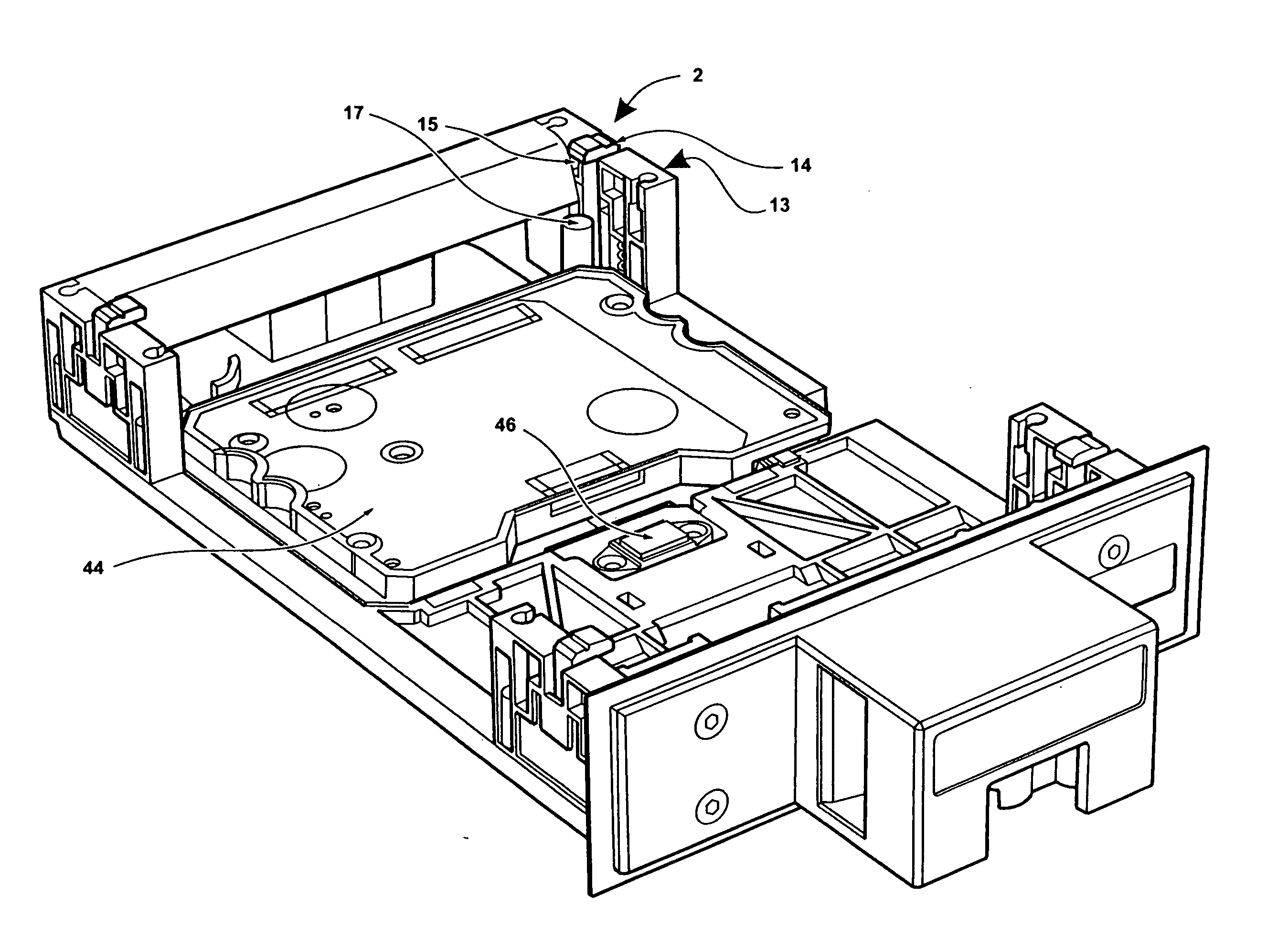
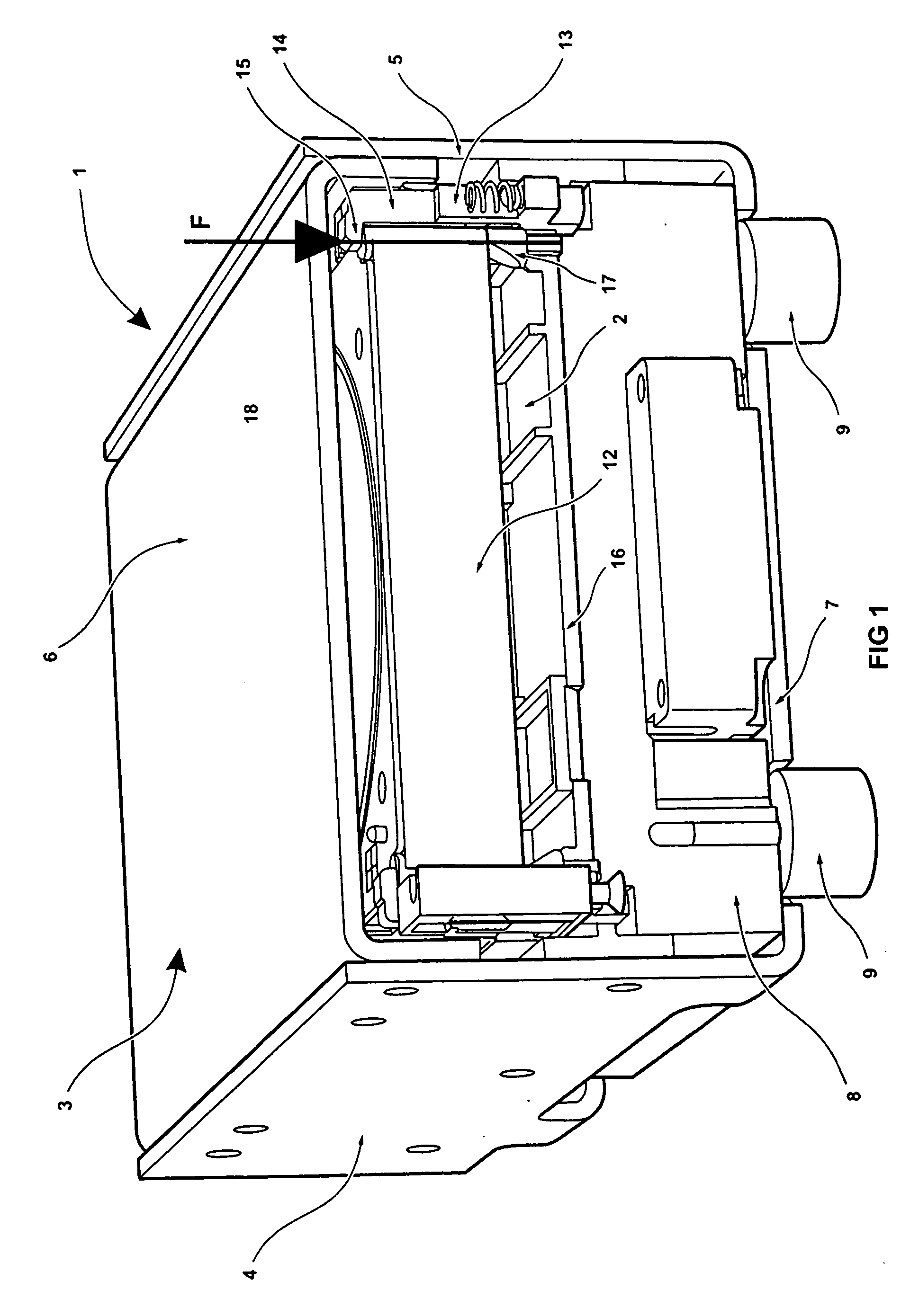
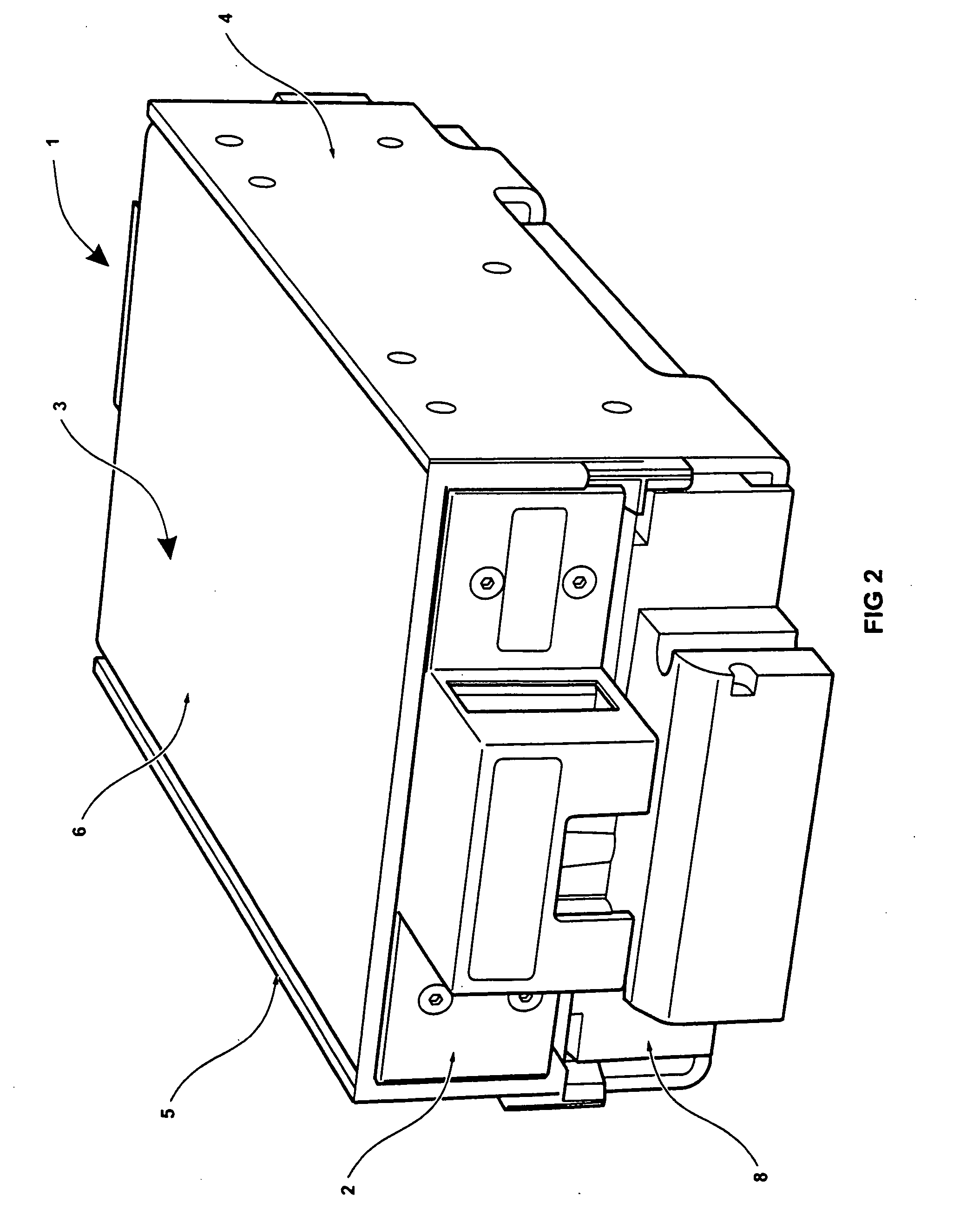
[0067] Referring initially to FIGS. 1 to 4, there is shown a disk drive support assembly 1 having a disk drive carrier 2 removably mounted therein. The assembly 1 has a housing or “cage”3 which has two opposed sides 4,5, a lid 6 and a base 7. Mounted internally in the lower part of the cage 3 is a relatively massive block 8, which may be made of a high density material, such as steel or granite for example. The disk drive carrier 2 is received internally in the upper part of the cage 3.

[0068] The relatively massive block 8 is mounted on vibration-damping mounts 9 which pass through corresponding apertures (not shown) in the base 7 of the cage 3. The vibration-mounting mounts 9 are preferably made of an elastomeric material, such as Sorbothane (trade mark), which is preferably under some 20% compression. As will be discussed further below, the cage 3 may be mounted in a cell in a rack of plural cells. The mounting is such that the vibration-damping mounts 9 sit on the floor of the c...


PUM


Abstract

A disk drive support assembly has a clamp arrangement for releasably clamping a disk drive to a massive block. The clamp arrangement may be an inflatable actuator that is operable to clamp the disk drive to the block via a disk drive carrier. Various clamp assemblies for clamping a disk drive to a substrate, such as a disk drive carrier, are also disclosed. A disk drive carrier that can be adapted for use with different types of disk drive is also disclosed. Such disk drives include those that provide for electrical and/or data connections under the disk drive, those that provide for electrical and/or data connections at the rear of the disk drive, and those that have their own so-called product card associated therewith.

Description

[0001] The present invention claims priority from U.S. Ser. No. 60 / 478,467 filed Jun. 16, 2003, the entire content of which is incorporated herein in its entirety.FIELD OF THE INVENTION [0002] The present invention relates to a disk drive support assembly, a clamp assembly, and a disk drive carrier. DESCRIPTION OF RELATED ART [0003] There are a number of applications when it is necessary to mount a disk drive in some other apparatus. These include for example when the disk drive is tested during manufacture and when the disk drive is in use for data storage applications or the like. A particular application is when servo tracks are written to the disk drive during the manufacturing process. Servo tracks are used during normal use of the disk drive to enable the read / write head (also known as the product head) of the disk drive to know its location over the disk(s). Two particular emergent technologies for writing servo tracks are the self-servo writing process and the self-servo fil...

Claims


Application Information

Patent Timeline
IPC IPC(8): G06F1/18G11B5/596
CPCG06F1/184G11B5/59633G06F1/187
Inventor KAY, ALEXANDER S.MUNCASTER, TIMOTHY J.NINEHAM, ANDREW J.ATKINS, ANDREW W.
Owner XYRATEX TECH LTD
Why Eureka
Try Eureka