Pipe coupler with tongue and groove sealing sleeve

a sealing sleeve and pipe coupler technology, applied in the direction of hose connection, machine/engine, mechanical apparatus, etc., can solve the problems of the past art leaving much to be desired with respect to the present day requirements, and achieve good sealing, high clamping load, and high pull-apart strength

Inactive Publication Date: 2006-04-11
BREEZE TORCA PRODS
View PDF30 Cites 25 Cited by
  • Summary
  • Abstract
  • Description
  • Claims
  • Application Information

AI Technical Summary

Benefits of technology

[0008]In accordance with this invention, a coupler is provided for joining a pair of pipes in a butt joint which provides a good seal against fluid leakage and exhibits high pull-apart strength. This is accomplished by providing an improved sealing sleeve in a band clamp which is capable of applying a high clamping load. Further, the invention is especially adapted for use in a coupler for application in vehicle engine exhaust systems.

Problems solved by technology

However, the prior art leaves much to be desired with respect to the present day requirements.

Method used


Image

  • Pipe coupler with tongue and groove sealing sleeve
  • Pipe coupler with tongue and groove sealing sleeve
  • Pipe coupler with tongue and groove sealing sleeve

Examples


first embodiment

of the Invention

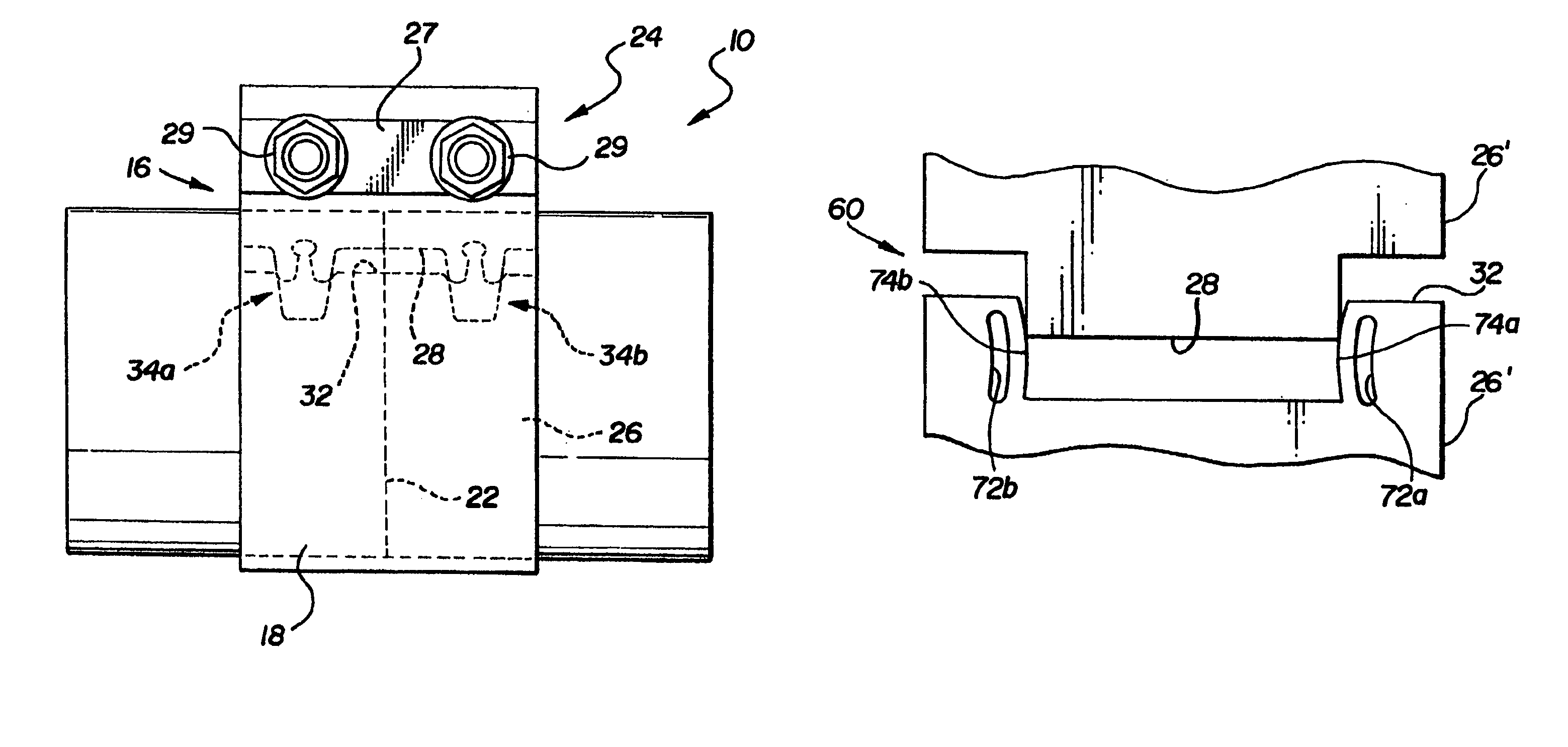
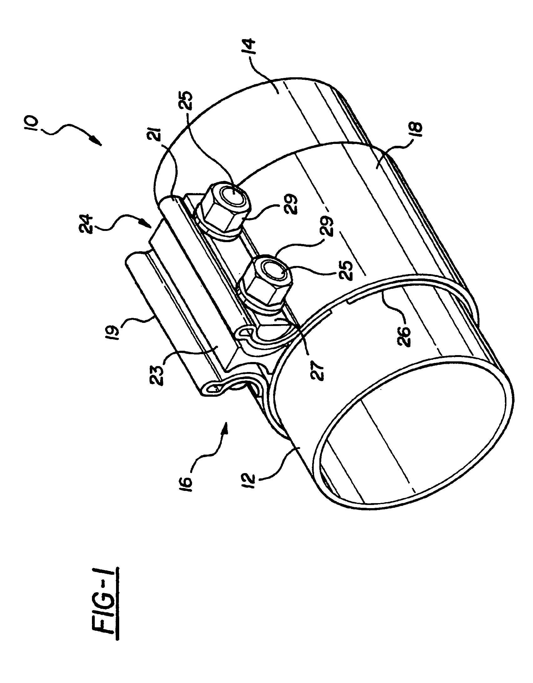
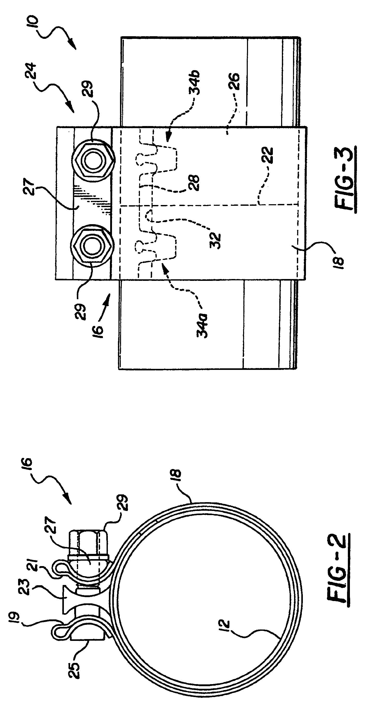
[0022]The first embodiment of the invention is shown in FIGS. 1–7. The coupler 10 is adapted to connect a pair of pipes 12 and 14 in a butt joint which provides a good gas seal and a strong mechanical connection between the pipes. The pipes 12 and 14 have the same nominal diameter, subject to manufacturing tolerances. The ends of the pipes 12 and 14 meet at a juncture 22 in axial alignment with each other. The coupler comprises a clamp 16 which includes a clamp band 18 adapted to encircle the pair of pipes and overlap the ends of the pipes. The clamp band 18 is formed as an open sleeve and terminates in laterally extending, opposed flanges 19 and 21. The clamp 16 also includes a tightening mechanism 24 connected with the clamp band for tightening the clamp to reduce the circumferential length of the clamp band. A split sealing sleeve 26 is disposed inside the clamp band 18 and has first and second circumferential ends 28 and 32 with seal structures, respectively, in ...

second embodiment

of the Invention

[0029]A second embodiment of the invention will now be described. The coupler of the second embodiment is of the same construction as the coupler of FIGS. 1–7 except for a different construction of the split sealing sleeve 26′ which is shown in FIGS. 8 and 9. The sealing sleeve 26′ is of the same type as the first embodiment but has only one tongue and groove joint 60. The Joint 60 comprises a groove 62 defined by one end of the sleeve 26′ and a tongue 64 defined by the other end of the sleeve. The groove 62 has oppositely disposed side edges 66a and 66b. The tongue 64 has oppositely disposed side edges 68a and 68b. The side edges of the groove 62 have an arcuate configuration which extends inwardly of the groove such that the groove is wider at its open end and at its closed end than it is in the region therebetween. A relief slot 72a is disposed adjacent the side edge 66a and extends in the same direction and thereby forms a spring edge member 74a. Similarly, a rel...


PUM

PropertyMeasurementUnit
angleaaaaaaaaaa
angleaaaaaaaaaa
angleaaaaaaaaaa

Abstract

A coupler for use in joining two pipes in a butt joint. The coupler includes a band clamp and a split sealing sleeve disposed inside to band clamp for encircling the abutted ends of the pipes. The split sealing sleeve has a tongue-and-groove sealing joint at the confronting free ends of the sleeve. The sealing joint has a member at the mating edges to provide a resilient interference fit of the tongue-and-groove.

Description

CROSS REFERENCE TO RELATED APPLICATION[0001]This application is a continuation of U.S. application Ser. No. 09 / 886,793 filed Jun. 21, 2001, now U.S. Pat. No. 6,758,501, which claims the benefit of Provisional Patent Application 60 / 213,791 filed Jun. 23, 2000.TECHNICAL FIELD[0002]This invention relates to pipe couplings; more particularly, it relates to a type of pipe coupling which is especially adapted for joining two pipe ends in a butt joint. This type of pipe coupling is sometimes referred to in the trade as a pipe coupler.BACKGROUND OF THE INVENTION[0003]There is a need, especially in the automotive industry, for a pipe coupling for connecting two pipes together in a vehicle engine exhaust system. For example, it is becoming common practice in the repair or servicing of an automobile exhaust system to replace the muffler by cutting the pipe between the muffler and the catalytic converter and attaching a new muffler by use of a special coupling which is herein referred to as a c...

Claims


Application Information

Patent Timeline
Patent Type & Authority Patents(United States)
IPC IPC(8): F16L21/00F16L25/00F01N13/08F16L21/06
CPCF16L21/005F16L21/065F01N13/1872F01N13/1811Y10S285/913F16L21/06F16L21/02F16L21/00F16L19/00
Inventor AMEDURE, MICHAEL E.IGNACZAK, BRIAN T.
Owner BREEZE TORCA PRODS
Why Eureka
Try Eureka