Bio-mask

a technology of breathing mask and sensor, which is applied in the field of breathing mask, can solve the problems of affecting the use of monitoring equipment, impede the use of such monitoring equipment, and inconvenient for patients and health care workers, and achieve the effect of easy and quick application of all sensors

Inactive Publication Date: 2007-04-17
COMPUMEDICS
View PDF25 Cites 108 Cited by
  • Summary
  • Abstract
  • Description
  • Claims
  • Application Information

AI Technical Summary

Benefits of technology

[0009]The invention relates to providing sensors in breathing masks to make it easy to monitor a patient. The mask has a soft pliable seal material around its perimeter in contact with the patient's face to form a secure seal therewith. Sensors may be recessed into the soft pliable seal material at the surface for contact with the skin of the user when the mask is applied to the user's face. The wiring for the sensors may be inside the soft pliable seal material insulating the wires from damage during use of the mask. Many sensors can be incorporated into the mask. Sensors may be placed on the perimeter or on other portions of the mask not in contact with the skin. Sensors may also be placed on straps or caps used in conjunction with the masks or on other devices used with the mask.
[0010]Monitoring of patients with sleep disorders, breathing disorders or for anesthesia is made easier and more convenient for the patient and for the health care provider since all the sensors needed are built into a mask which is easily and quickly placed on the patient with all the wiring to the sensors integral with the mask and accessed by a single plug.
[0012]Connections to outside sources of gases delivered to the mask are by a gas nozzle hook up on the mask. A connection to electrical power and data output cables are by a plug in to a cable connecting to the mask. Alternatively batteries in the mask and telemetry equipment in the mask can provide power and transmission of the data to a microprocessor or computer. For portability the microprocessor can be attached to the mask or be carried by the patient. Similarly a bottle of gas may be connected to the mask and carried by the patient to allow mobility of the patient while wearing the mask.
[0020]It is an object of the invention to easily and quickly apply all the sensors needed for monitoring the patient.

Problems solved by technology

However there is no known example of sensors built into breathing masks for monitoring or studying patients with breathing disorders.
The plurality of sensors and tangle of ensuing wires impede the usage of such monitoring equipment.
It is very inconvenient for the patient and the health care worker to attach a series of different devices to a patient to monitor a plurality of different parameters simultaneously.

Method used


Image

  • Bio-mask
  • Bio-mask
  • Bio-mask

Examples


Embodiment Construction

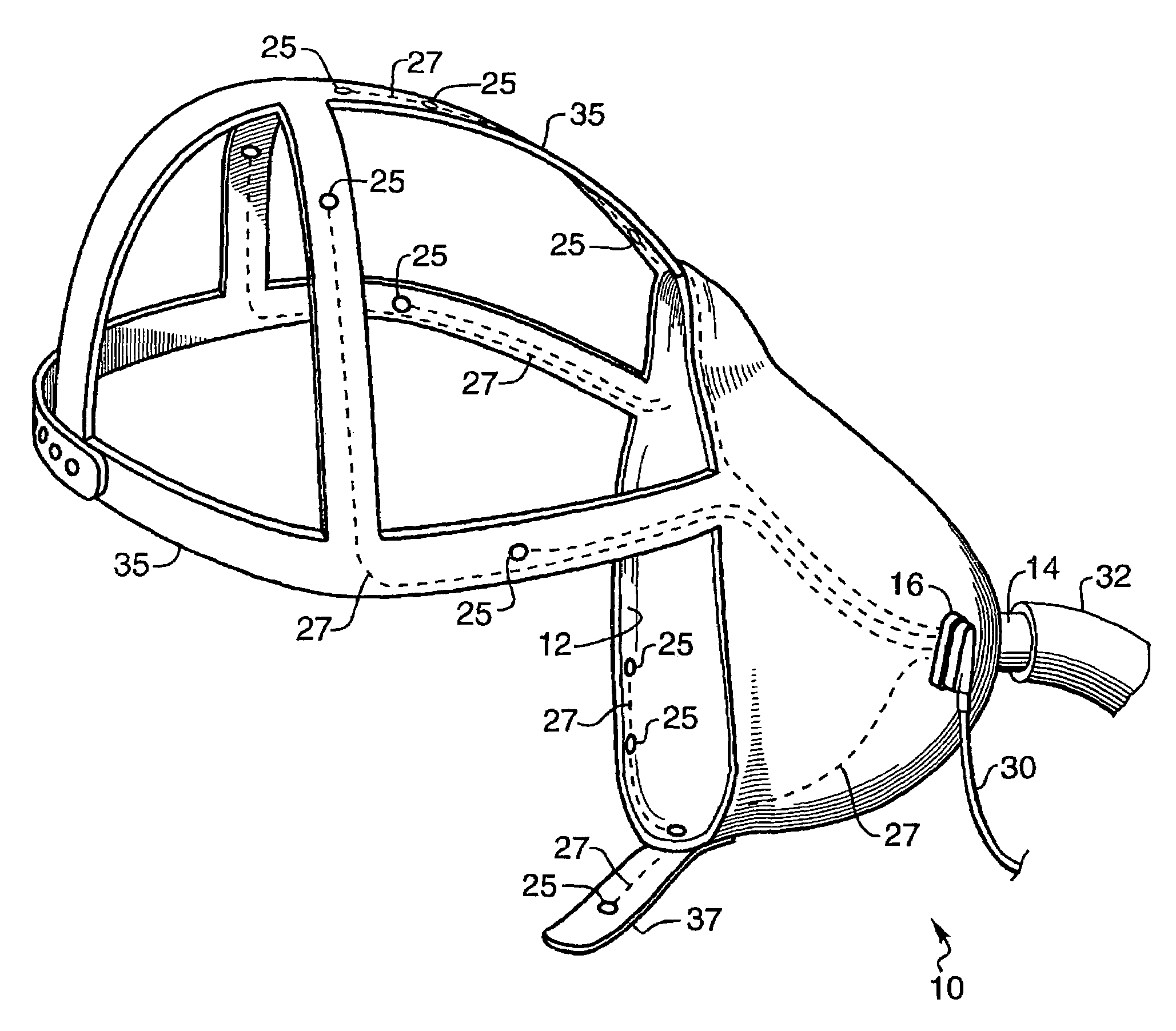
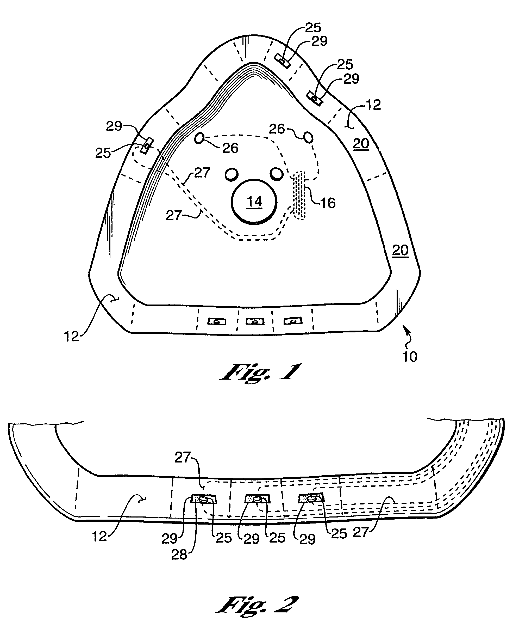
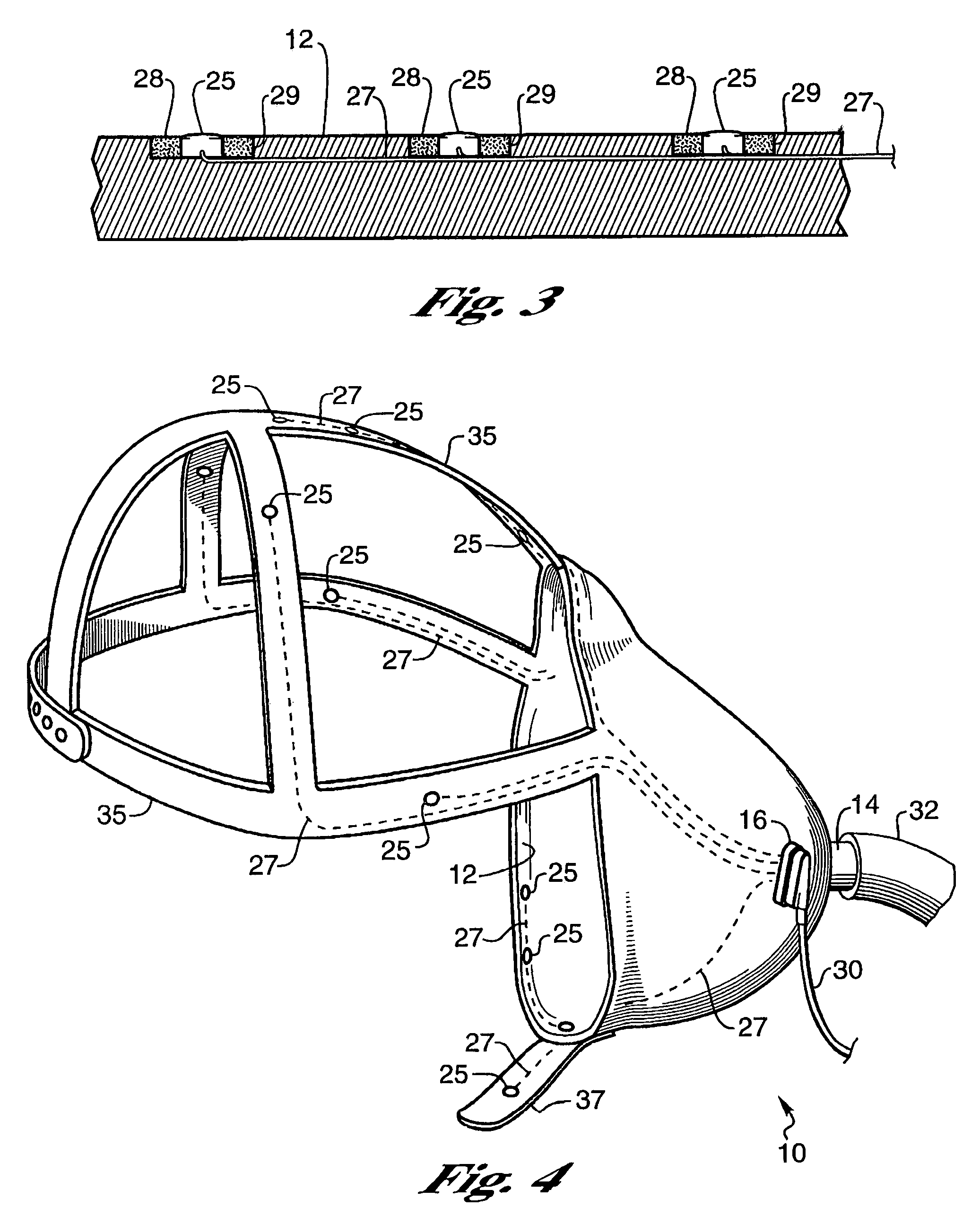
[0029]FIG. 1 shows the inside of mask 10 including the perimeter surface 12 which contacts the patient's face. The perimeter surface 12 has a plurality of zones 20. Each zone 20 having a sensor 25 in a recess 29 for measuring a parameter of the patient to be monitored or other data such as gas leakage. Other sensors 26 are on the mask 10 but not in contact with the patient's skin. These sensors 26 measure patient data or related data such as ambient light, gas pressure in the mask or ambient temperature. The mask 10 has a gas connector 14 for connecting a hose 32 to provide a gas to the mask 10 and a mask interface connector 16 for plugging in a cable 30 for a power supply and for data transmission.

[0030]In some embodiments of the invention the sensors 25 do not require an outside source of power as the sensors such as heat sensors and light sensors generate current.

[0031]The mask perimeter surface 12 is preferably made out of a soft pliable material such as silicone rubber for maki...


PUM


Abstract

The invention relates to a breathing mask for use in monitoring a patient. The mask can have sensors on the body of the mask and on the associated straps or caps. The mask can be used to monitor breathing problems or to monitor a patient during anesthesia. The data acquired from the mask sensors and related sensors can be stored or fed into a computer to analyze the patient's condition and provide feedback information.

Description

BACKGROUND OF THE INVENTION[0001]1. Field of the Invention[0002]This invention relates to a breathing mask with built in sensors for monitoring patients with sleep apnea, breathing disorders for use during anesthesia or ventilation support.[0003]2. Description of the Related Art[0004]Masks such as shown in U.S. Pat. No. 5,243,971 for applying a positive pressure to patients with apnea and other breathing disorders have been developed. These masks provide seals for preventing air from escaping from the mask at the junction of the mask and face. Other types of masks for gas delivery to a patient are also in common use.[0005]Measuring air flows to a patient has been accomplished by metering sensors in the air supply connected to the mask as in U.S. Pat. No. 5,503,146 or by belts around the patients chest to measure his breathing as in U.S. Pat. No. 5,131,399.[0006]Some devices such as in U.S. Pat. No. 5,507,716 provide sensors combined with sleep masks for covering the eyes of a patien...

Claims


Application Information

Patent Timeline
Patent Type & Authority Patents(United States)
IPC IPC(8): A62B9/00A62B18/02A61B5/08A61B5/087A61B5/296A61M16/00A61M16/01A61M16/06
CPCA61B5/04085A61B5/0878A61B5/6803A61M16/06A61M16/0683A61M16/0633A61B5/0476A61B5/0492A61M2230/04A61M2230/08A61M2230/10A61M2230/205A61M2230/30A61M2230/50A61M2230/60A61M2230/62A61M2230/63A61M16/0694A61M2016/0027A61M16/0858A61M2205/0238A61M16/0605A61M16/021A61B5/282A61B5/369A61B5/296A61B5/386
Inventor BURTON, DAVID
Owner COMPUMEDICS
Why Eureka
Try Eureka